Castor & Pollux kit build guide#
Before you build#
Welcome to the build guide for Castor & Pollux's DIY kit. We hope you have a great time putting this module together and a wonderful time using it.
Please read all instructions thoroughly before starting. If you have questions or run into trouble please reach out to us on discord or drop us an email at support@winterbloom.com
This build is a intermediate level kit. You should be comfortable soldering through-hole components and working near surface mount components. If you're not, we encourage you to try out some other kits first, like our Big Honking Button kit. Even if you've got some experience, we recommend taking a look at Adafruit's guide to excellent soldering to refresh your knowledge.
By the way, we program, test, and calibrate the main circuit board before sending it to you, so you don't have to worry about any of that- once you're done building you'll be good to go!
This build takes around one hour to complete.
Tools and materials required#
Before jumping in, make sure you have:
- Safety glasses. Yes, really.
- Proper ventilation - at least open a window or two.
- A soldering iron, like this one.
- Solder, we can recommend Adafruit's 60/40 no-clean rosin core solder.
- A small flat head screwdriver, like this one.
Fairy
We suggest using solder with "no clean" flux. If you use a different kind of flux, be sure to carefully clean the flux residue off based on the guidelines provided by the manufacturer of your solder. Take special care with the LEDs and potentiometers, as they can be damaged by water and flux cleaners.
Kit contents#
Your kit should contain the following items. If any are missing please email us at support@winterbloom.com.
- (1) Mainboard
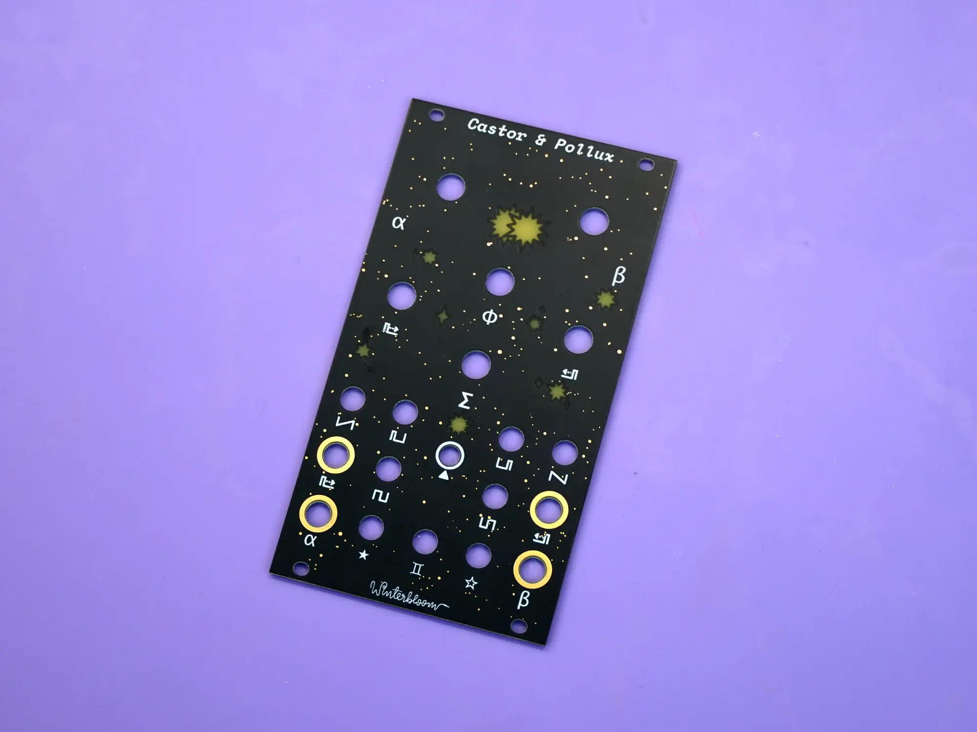
- (1) Faceplate
- (1) Expander board
- (1) Expander faceplate
- (1) Expander cable
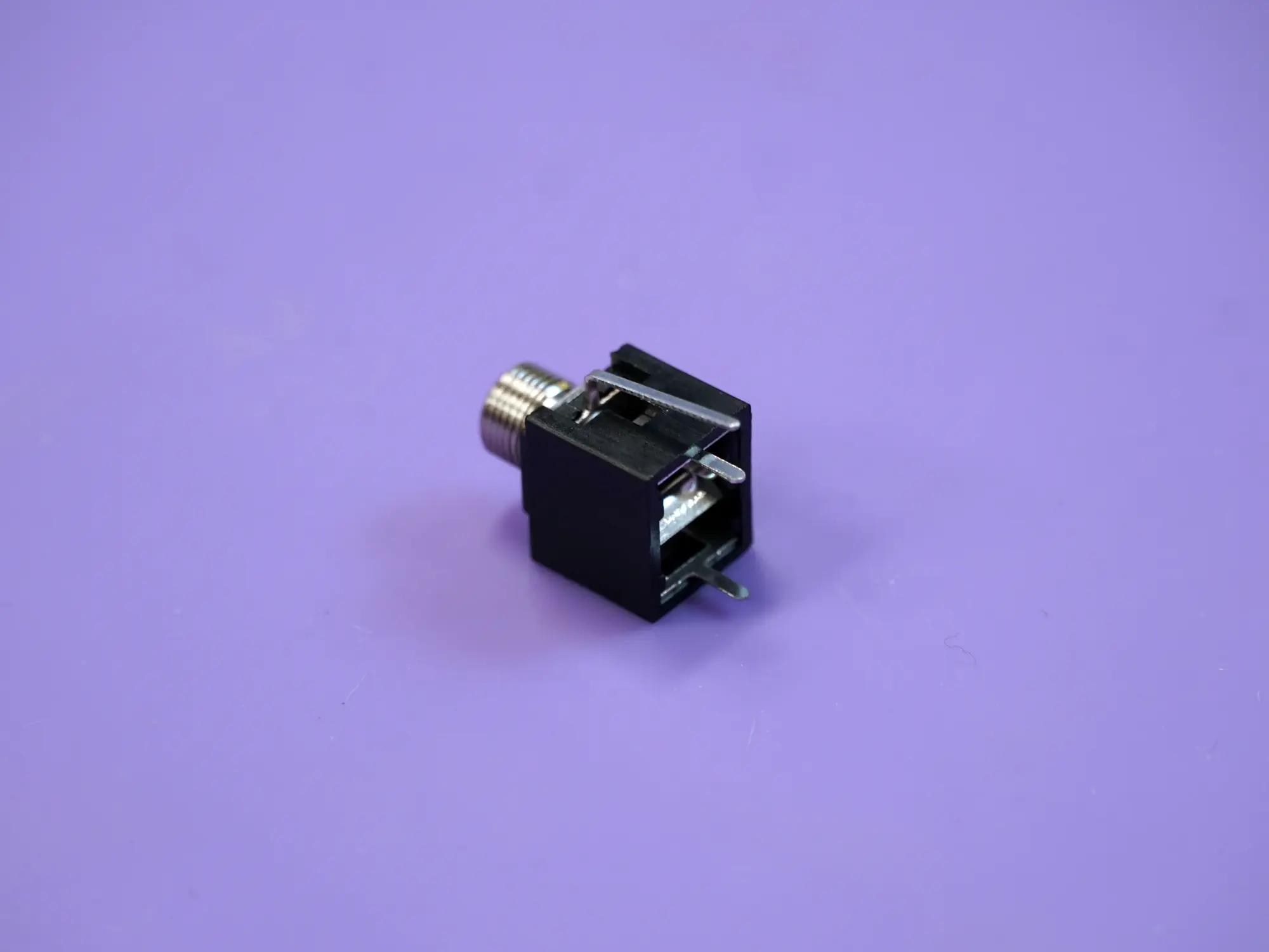
- (13) 1/8" jacks
- (13) Hex nuts for the 1/8" jacks
- (6) Tall trimmer pots
- (6) 9mm pots
- (6) Washers and nuts for the 9mm pots
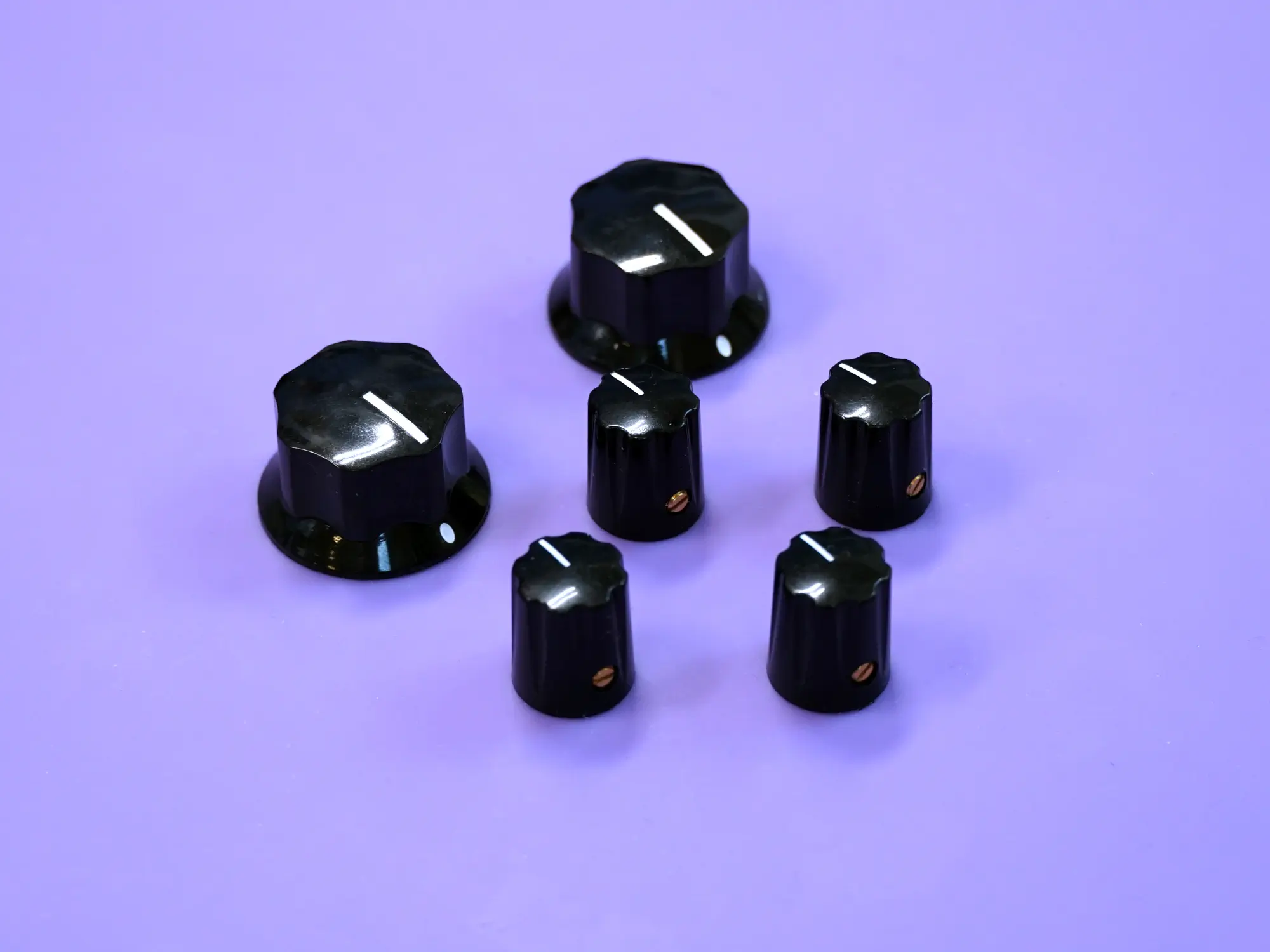
- (4) Small knobs
- (2) Large knobs
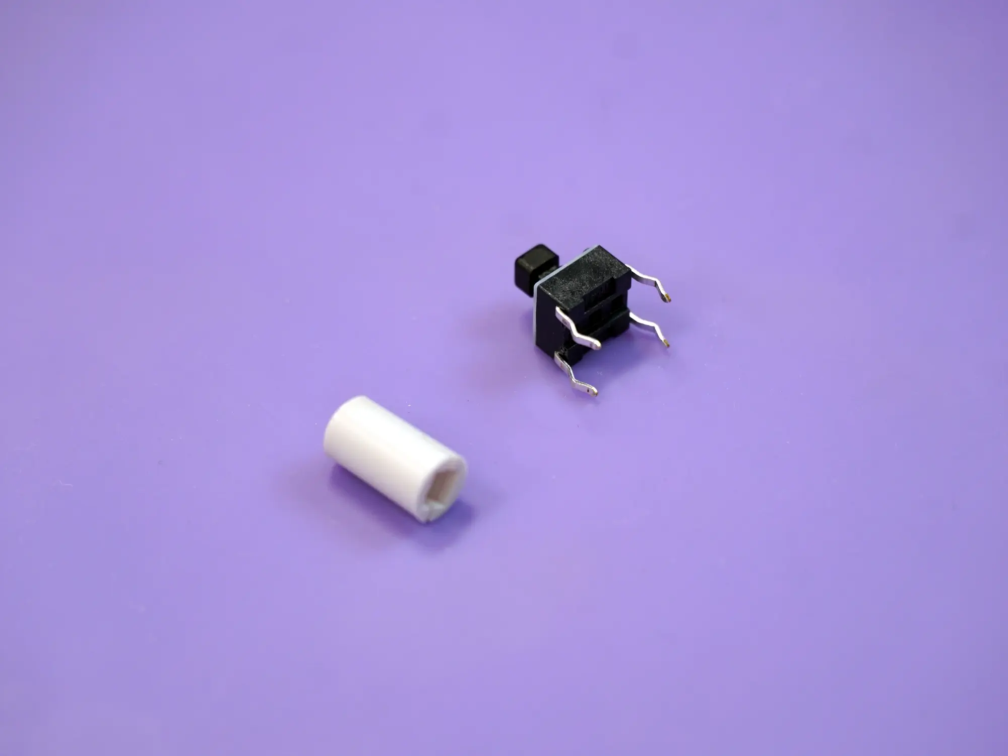
- (1) Tactile switch
- (1) Tactile switch cap
- (1) Eurorack power header
- (2) Rubber bands
Power header#
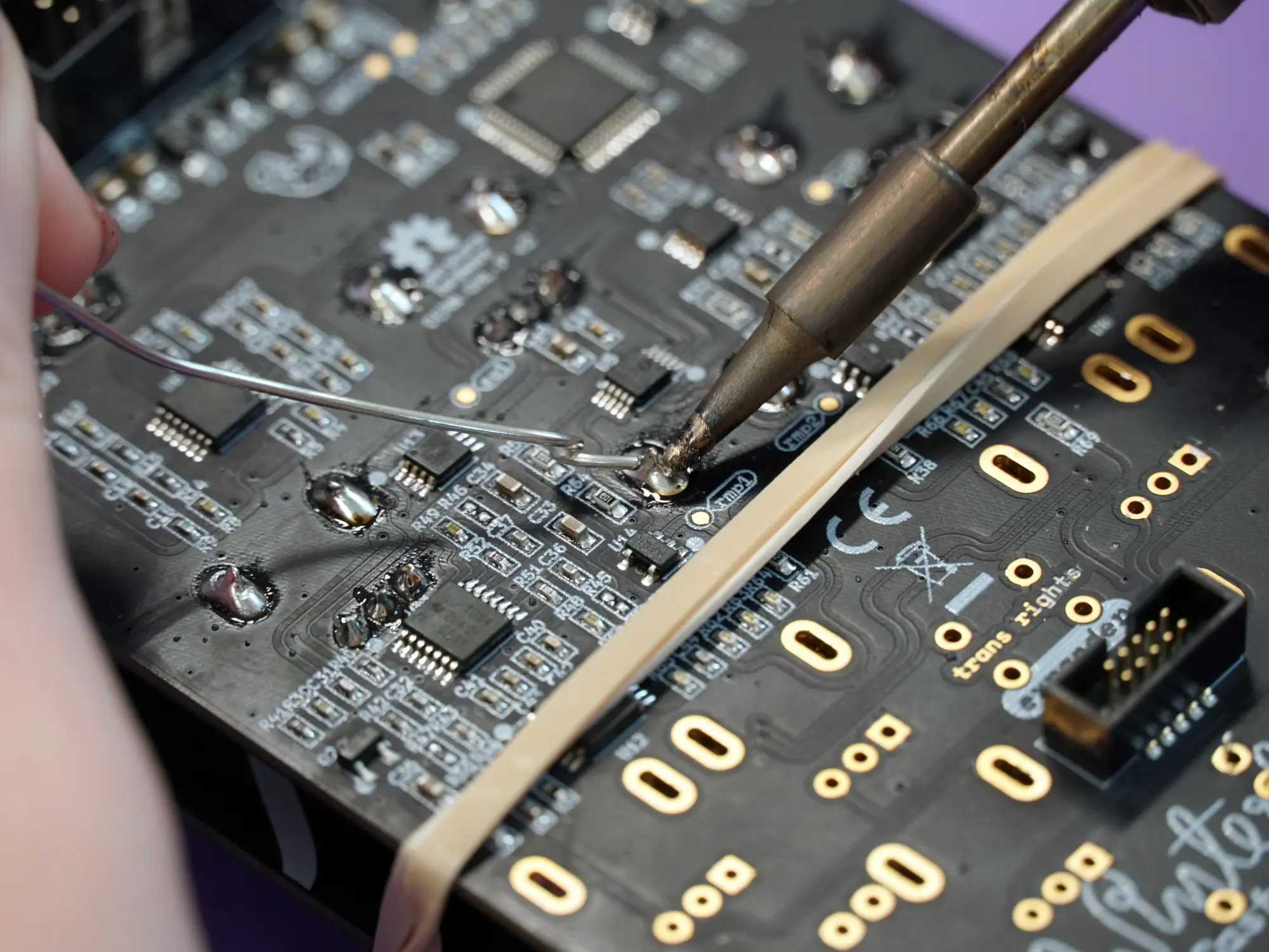
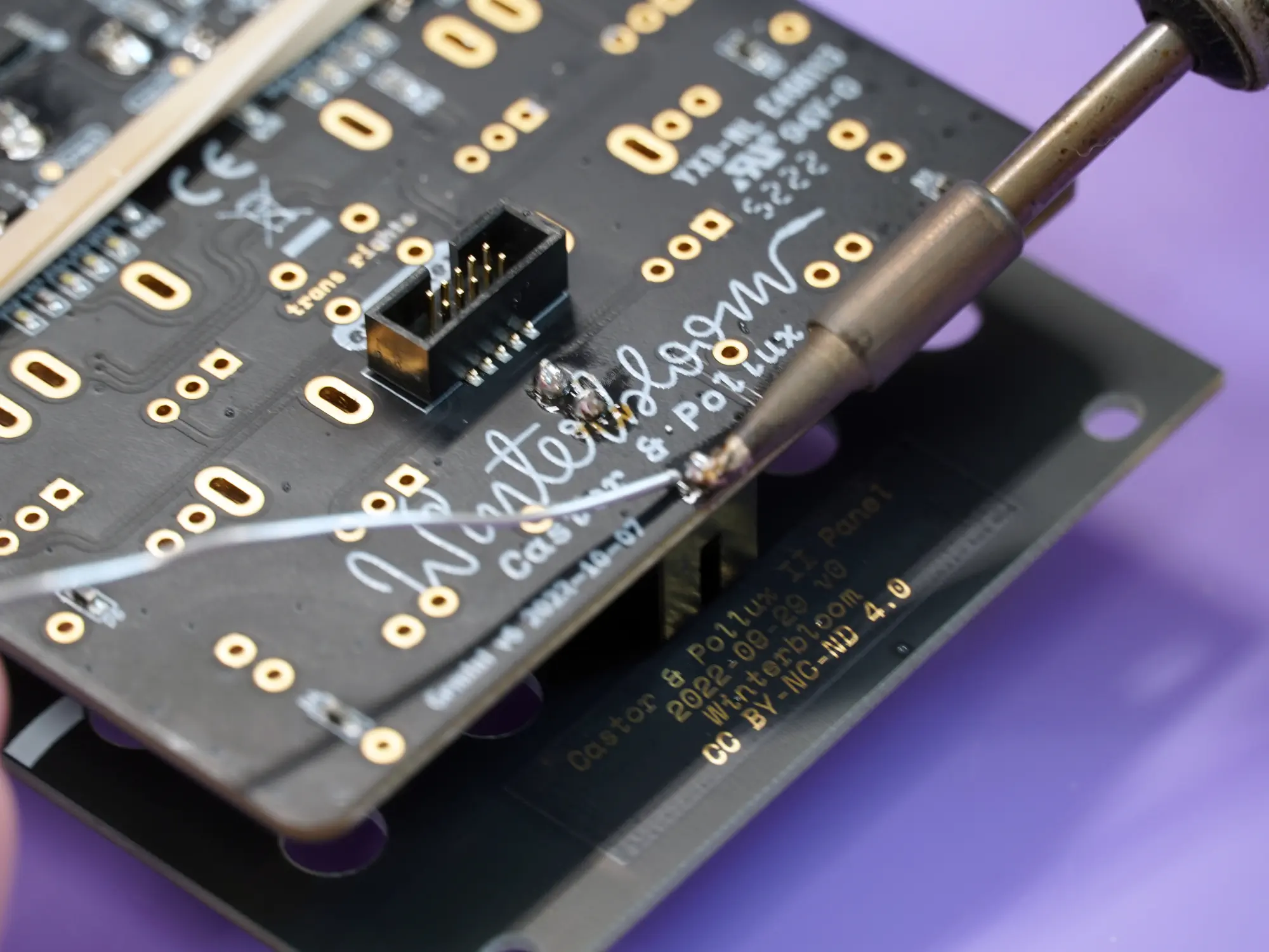
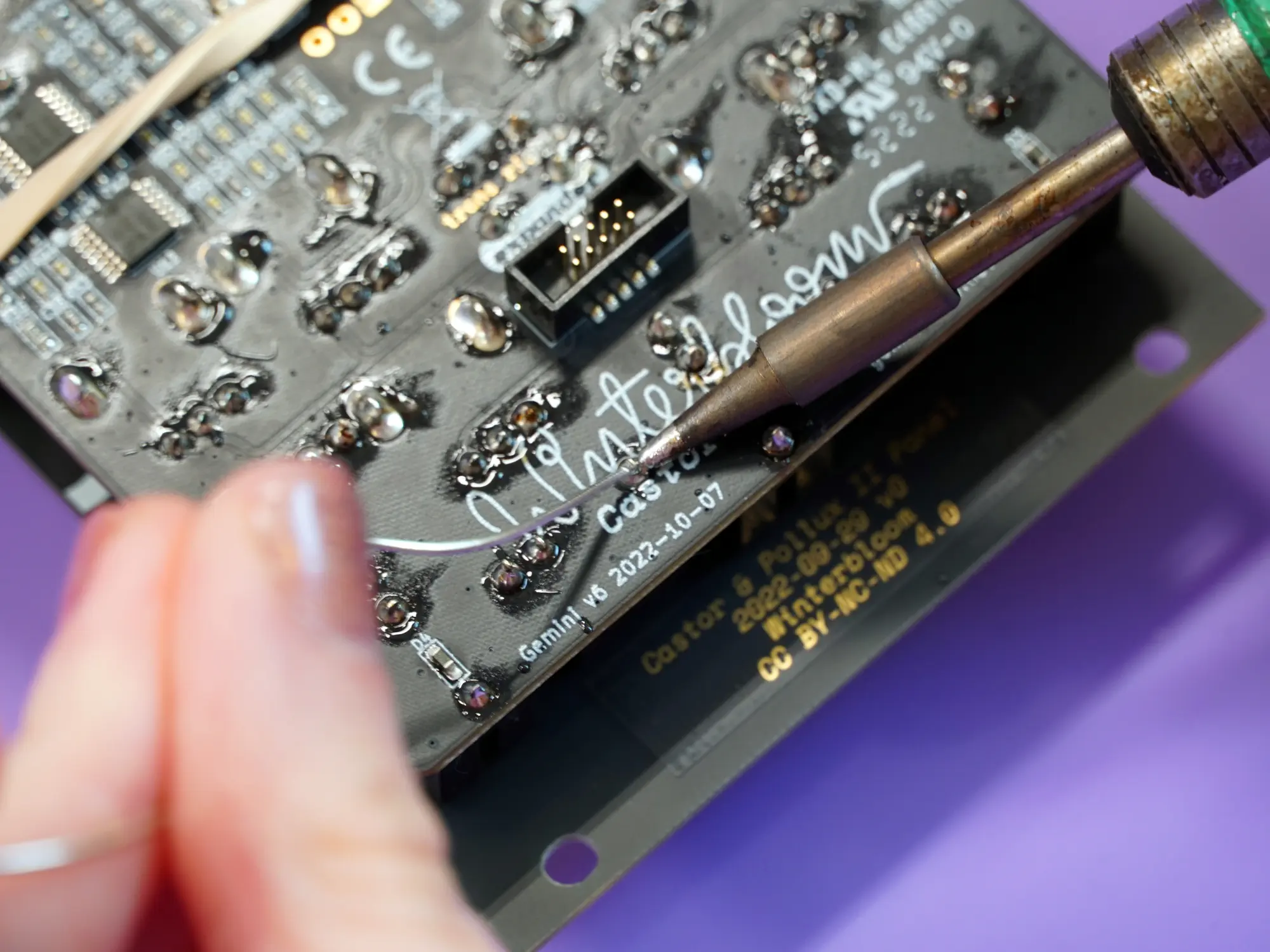
Your first task is to solder the 10-pin Eurorack power connector to the mainboard.
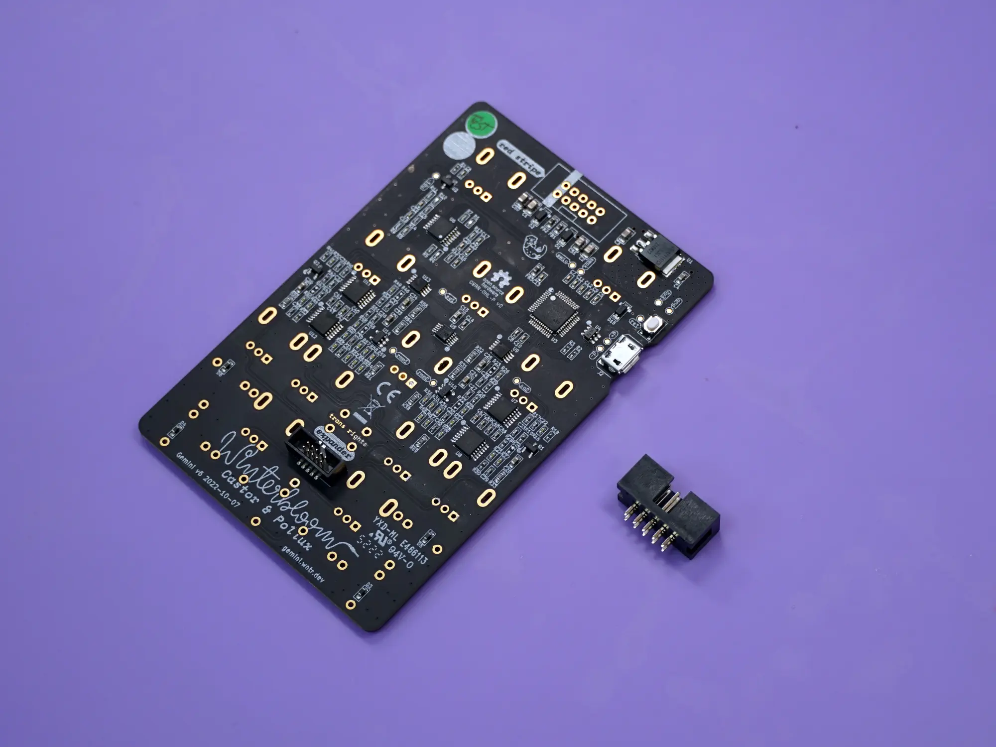
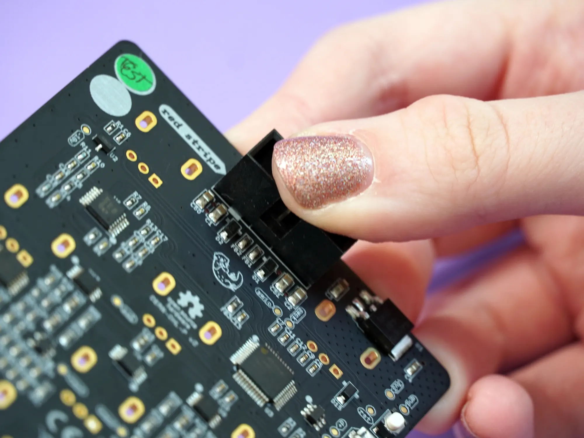
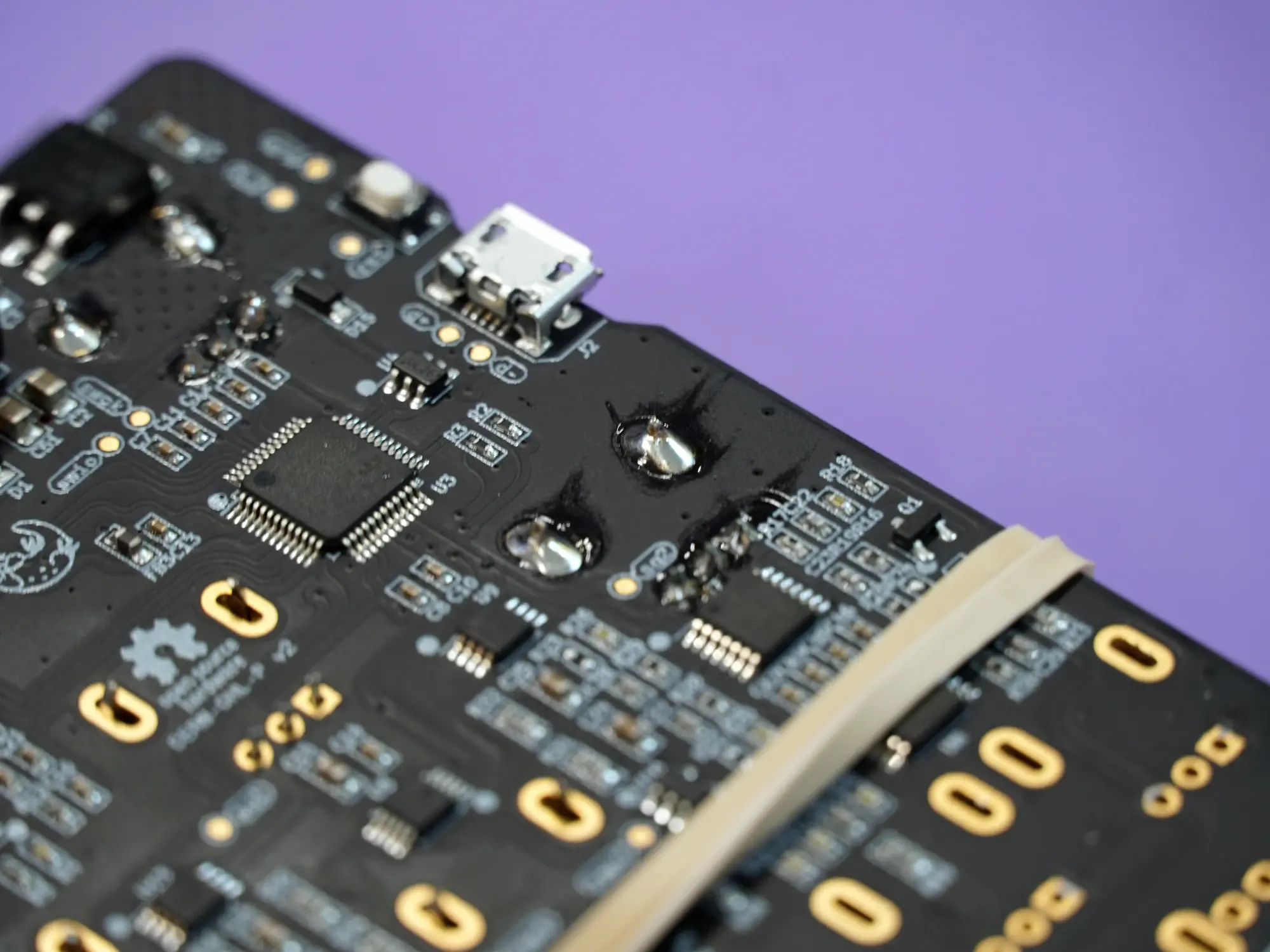
The power connector goes on the back side of the board. When placing note the notch in the outline on the board. You'll need to make sure the slot on the connector matches where the notch is on the outline.
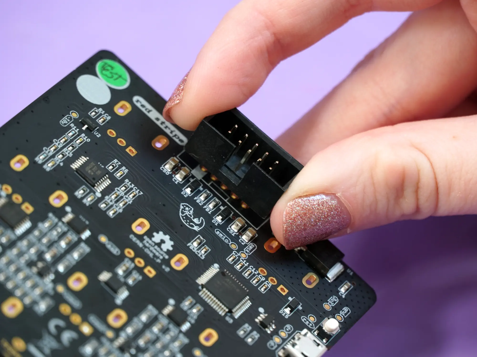
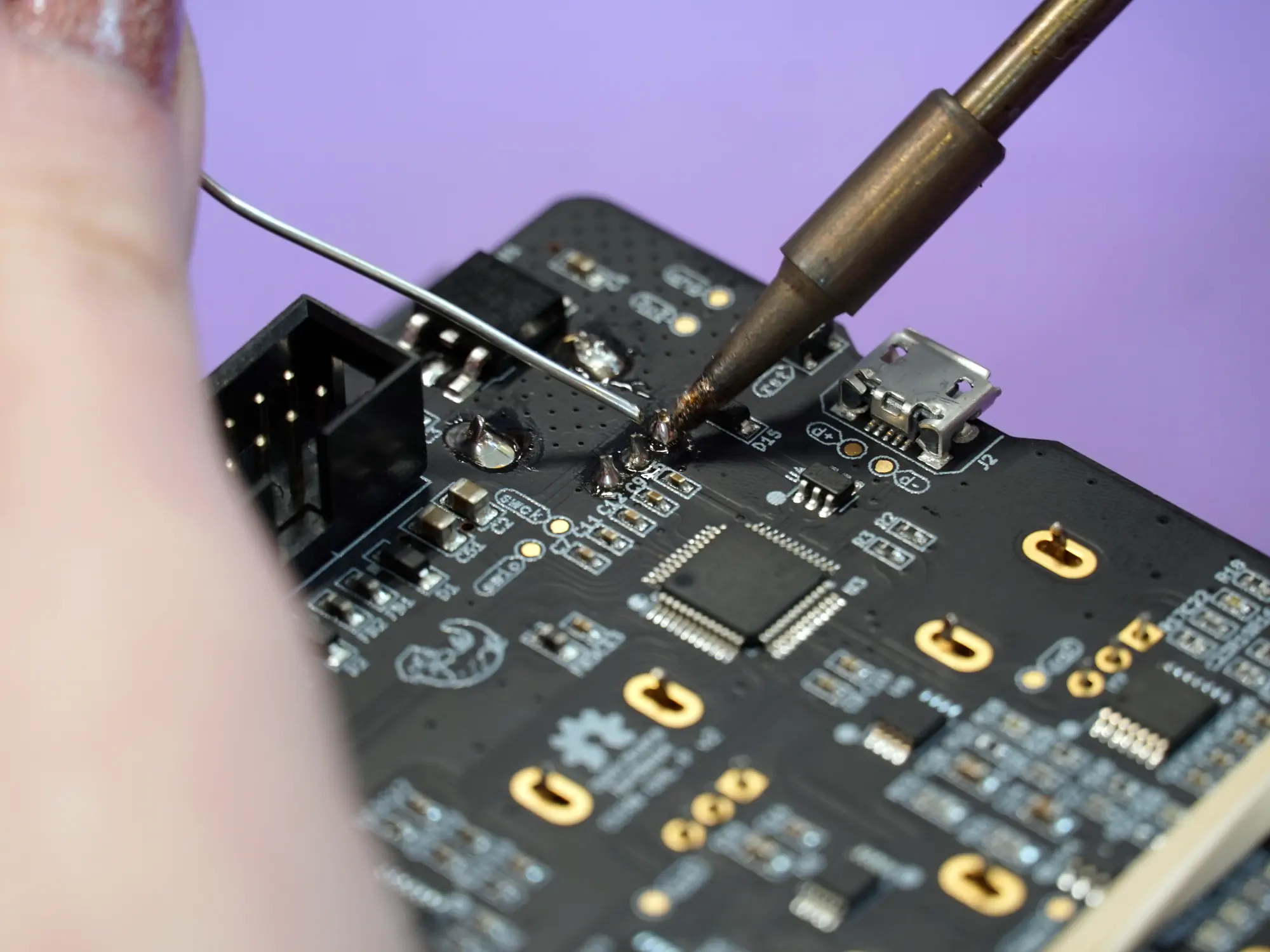
Once placed, make sure to push it flush against the board and then solder the 10 pins on the front side of the board. Be careful here and avoid touching the small components near the pins with your iron.
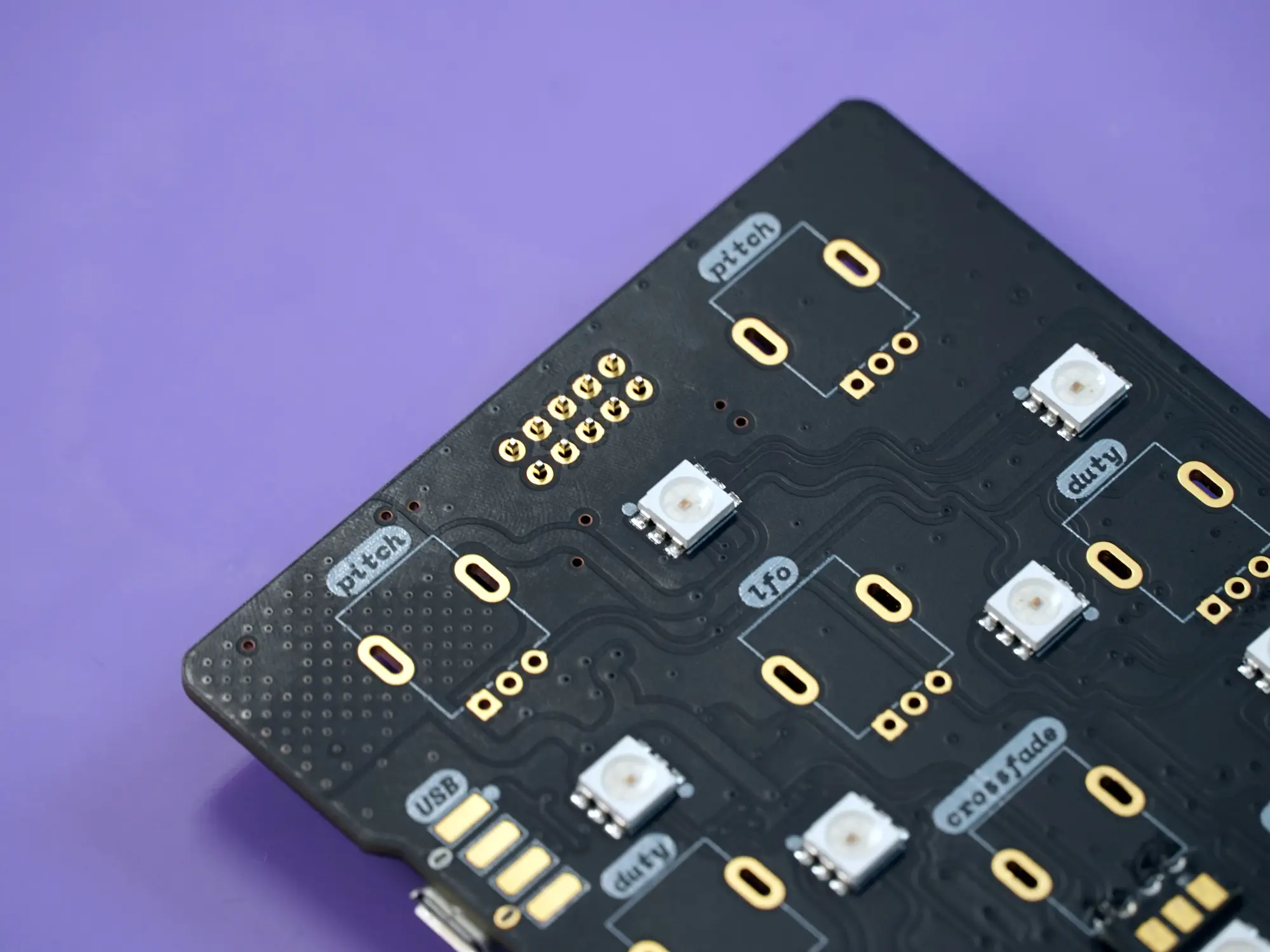
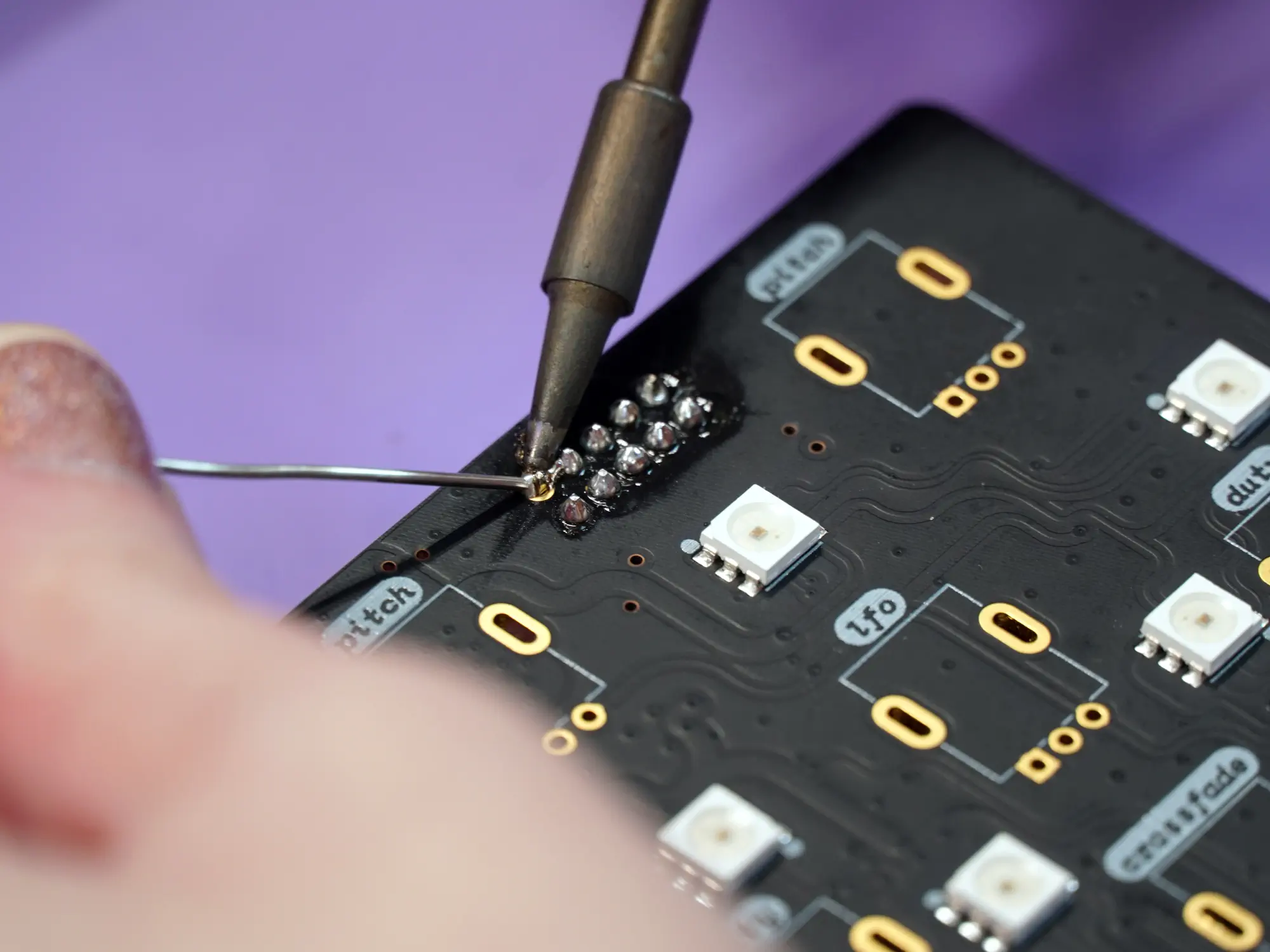
Watch out for those LEDs!
Avoid touching the LEDs with your iron- they really don't like being melted and they're very hard to replace.
9mm pots#
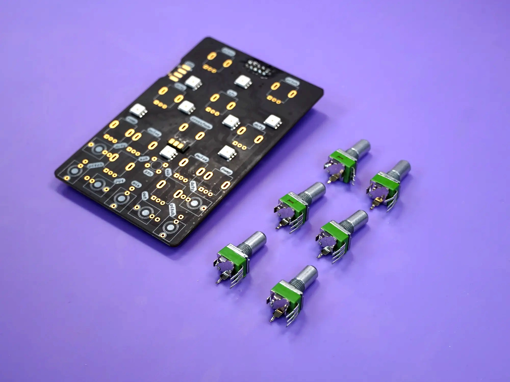
The next task is placing and soldering the six 9mm pots on the mainboard.
This step requires special care and attention to make sure that the front panel aligns correctly. Please make sure everything is correct before soldering anything in place.
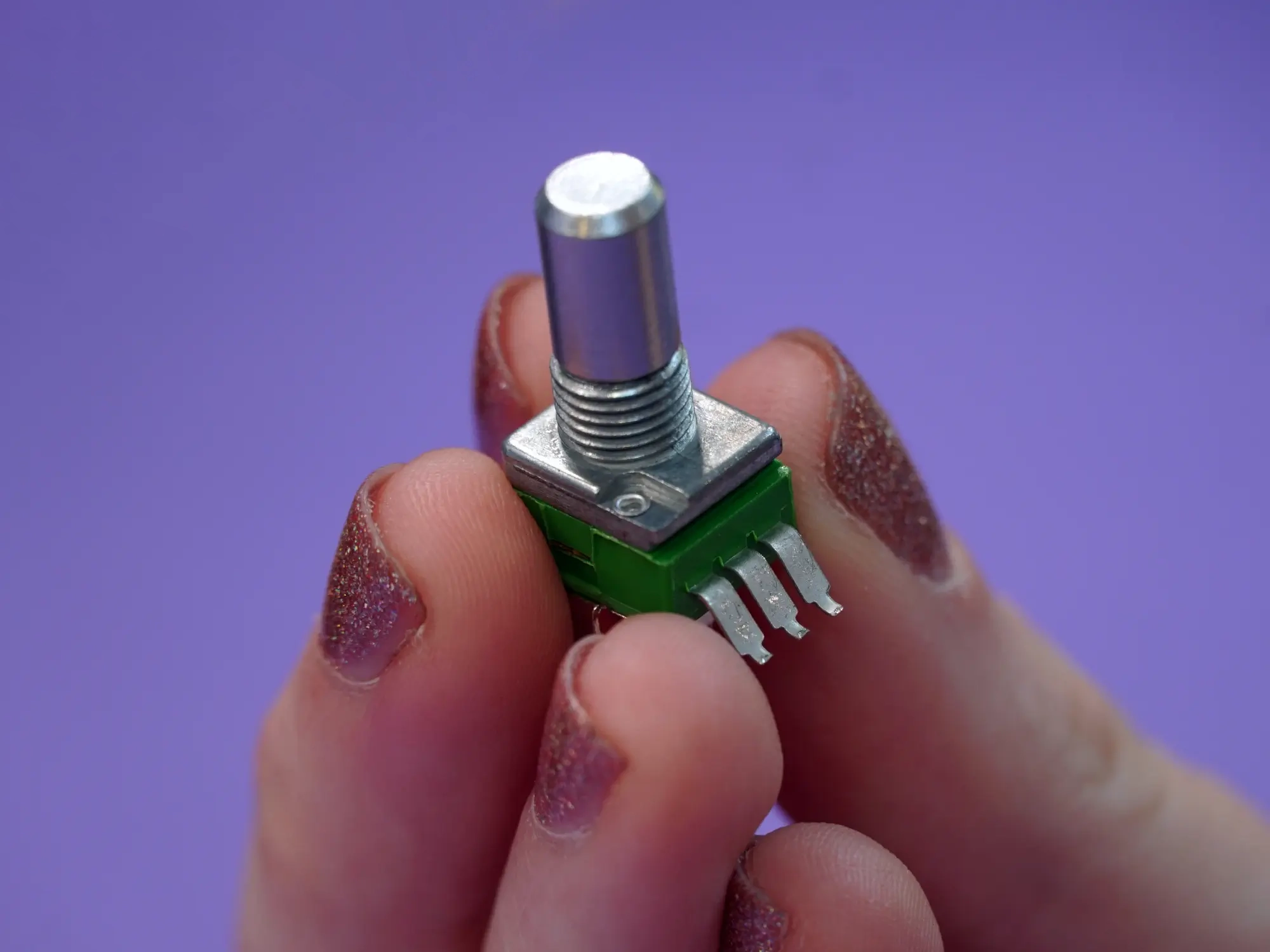
One of the six pots has been modified - its pins are shorter and bent outwards. Find this one and place it aside for the moment.
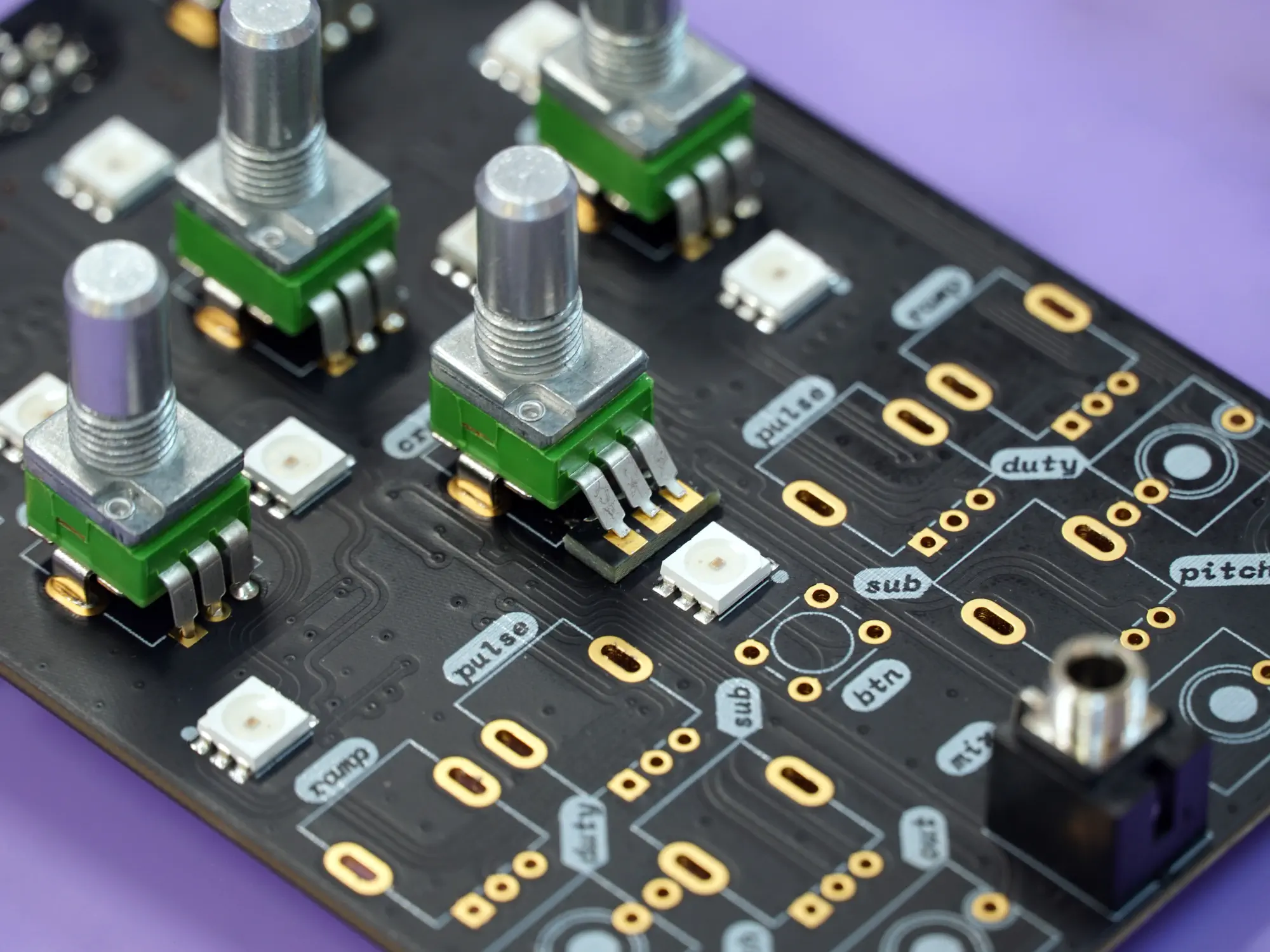
Place five of the six pots onto the mainboard in the spots labeled pitch, duty, and lfo. You may need to bend or straighten the mounting legs on the pots to get them in place.
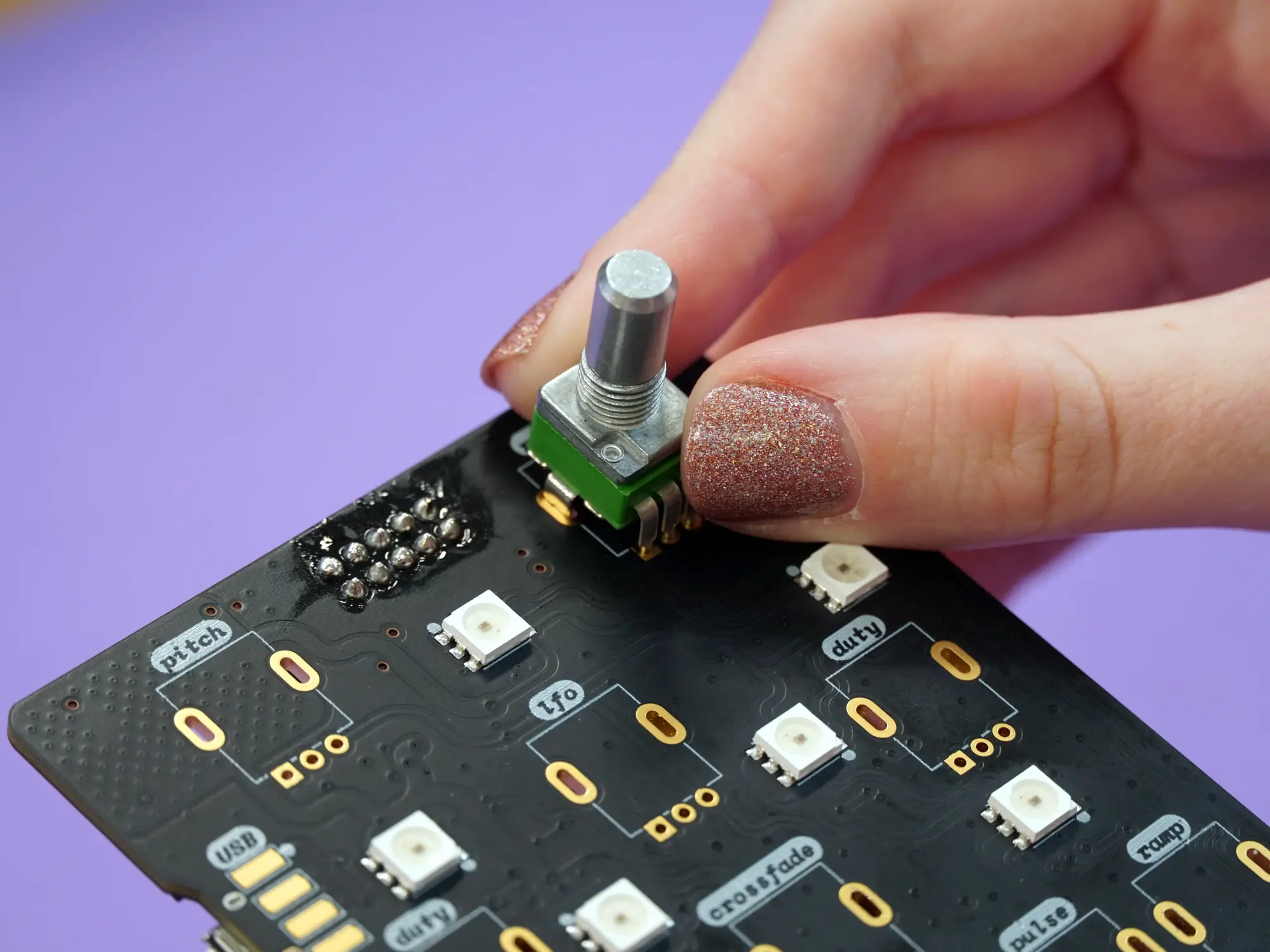
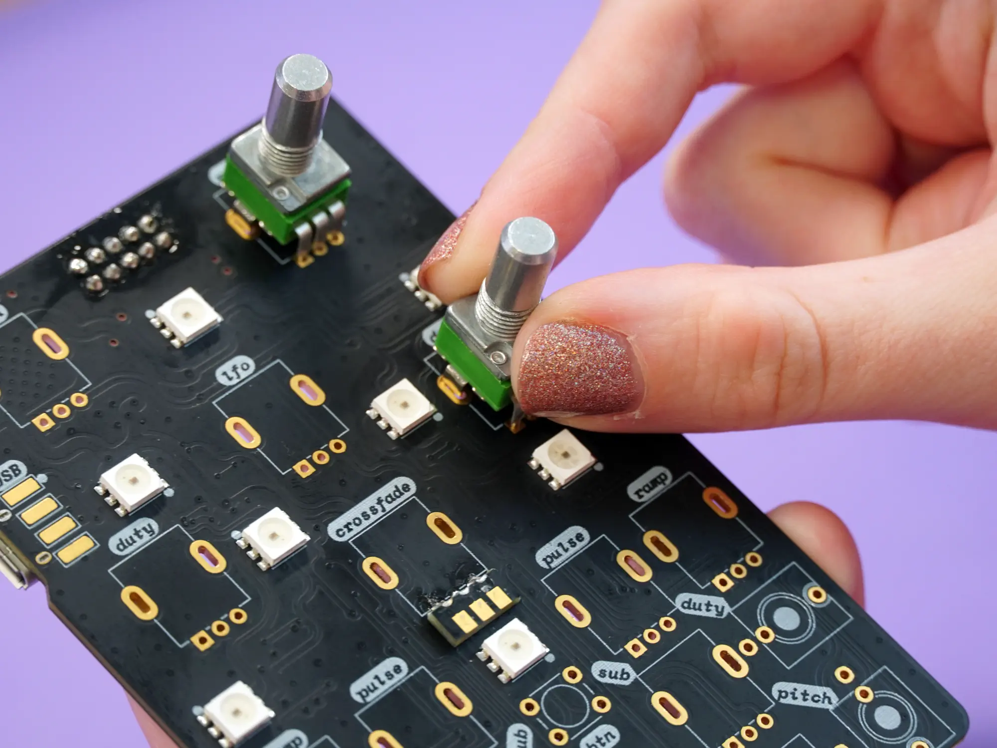
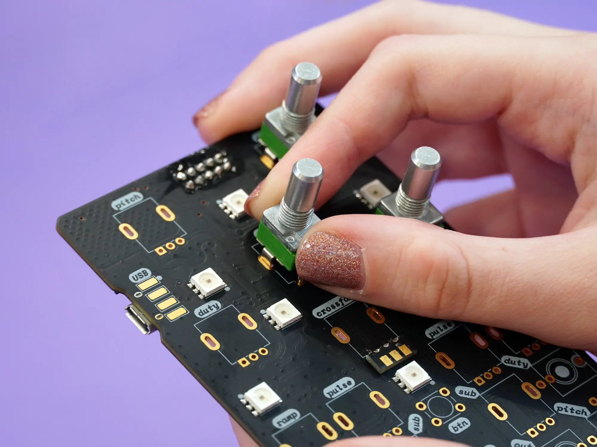
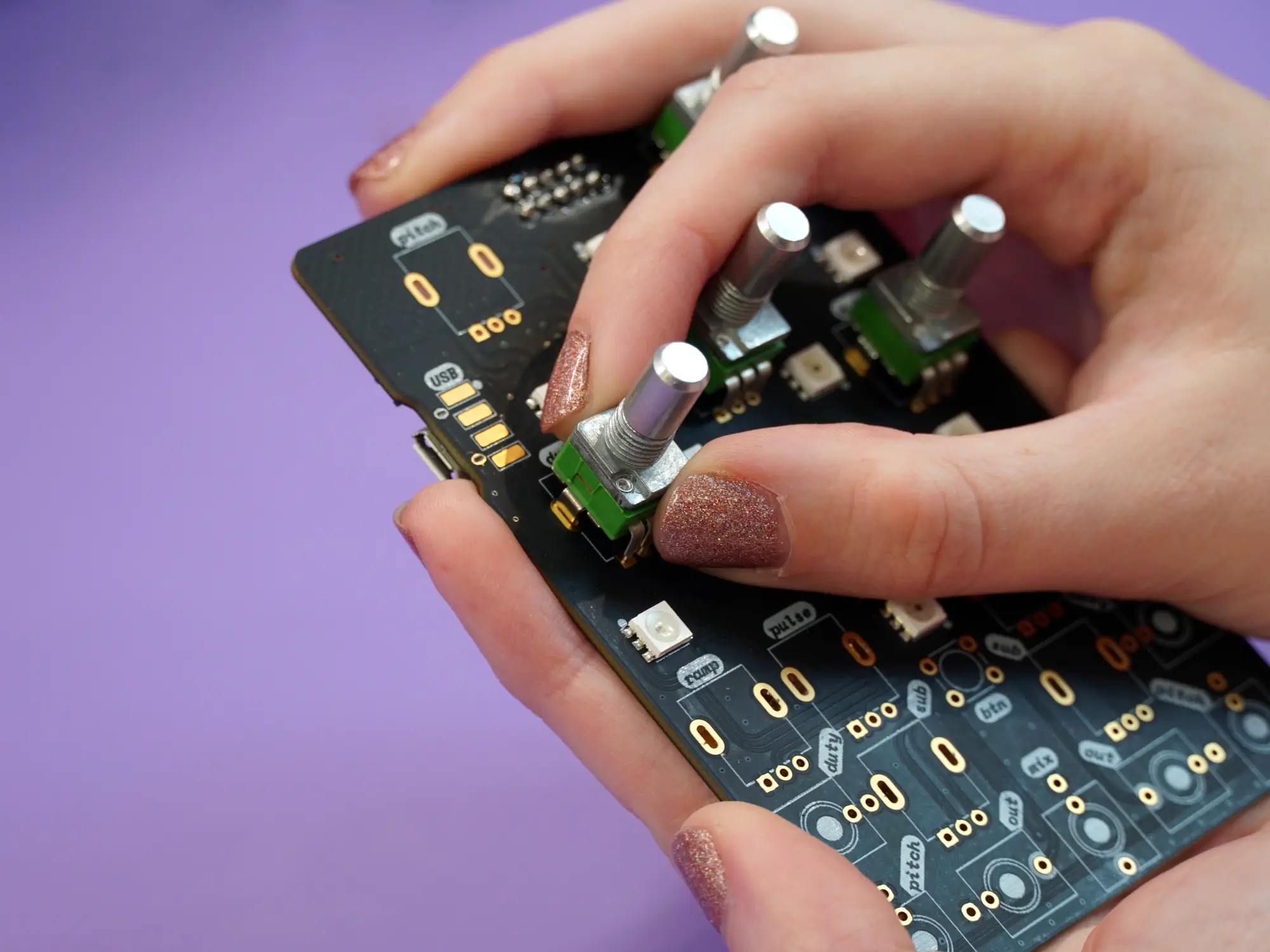
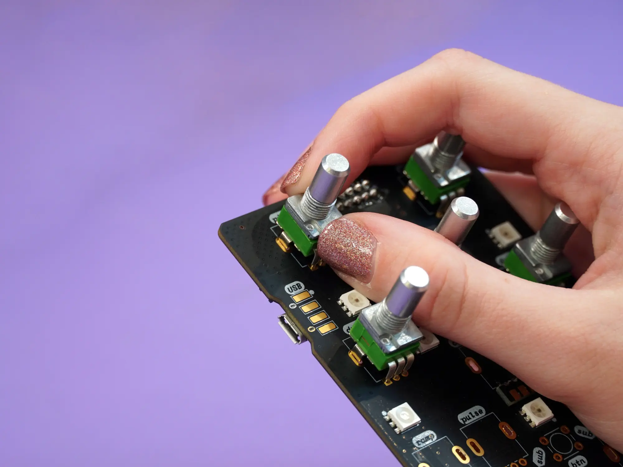
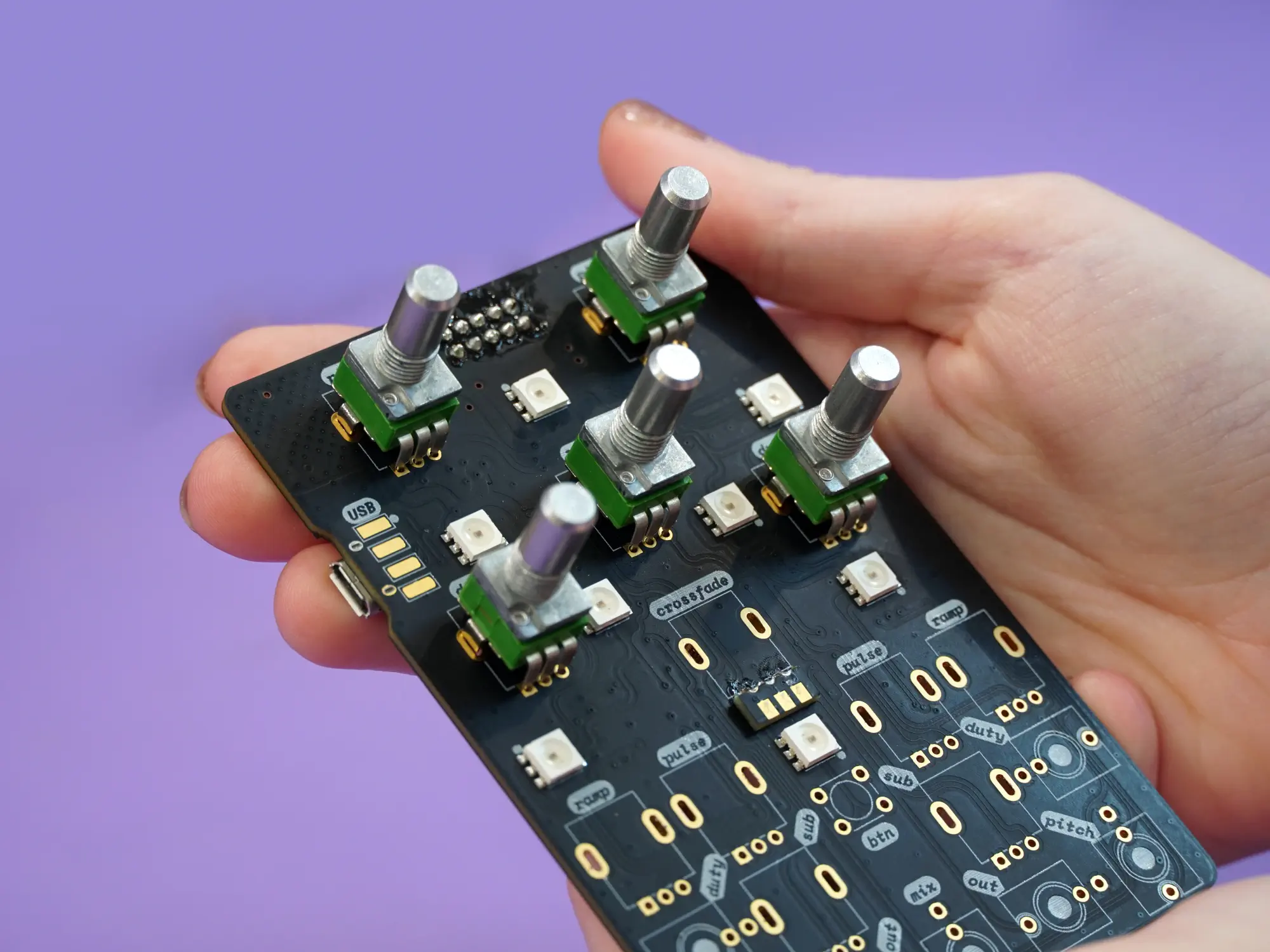
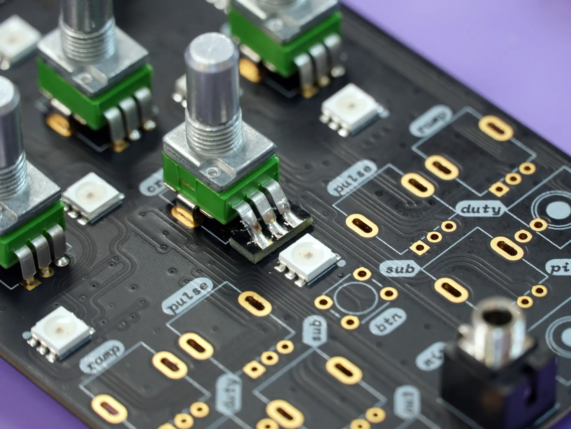
Take the remaining, modified pot and place it on the spot labeled crossfade. This pot will not be as secure as the others, but make sure the pins line up with the pads on the as board shown below.
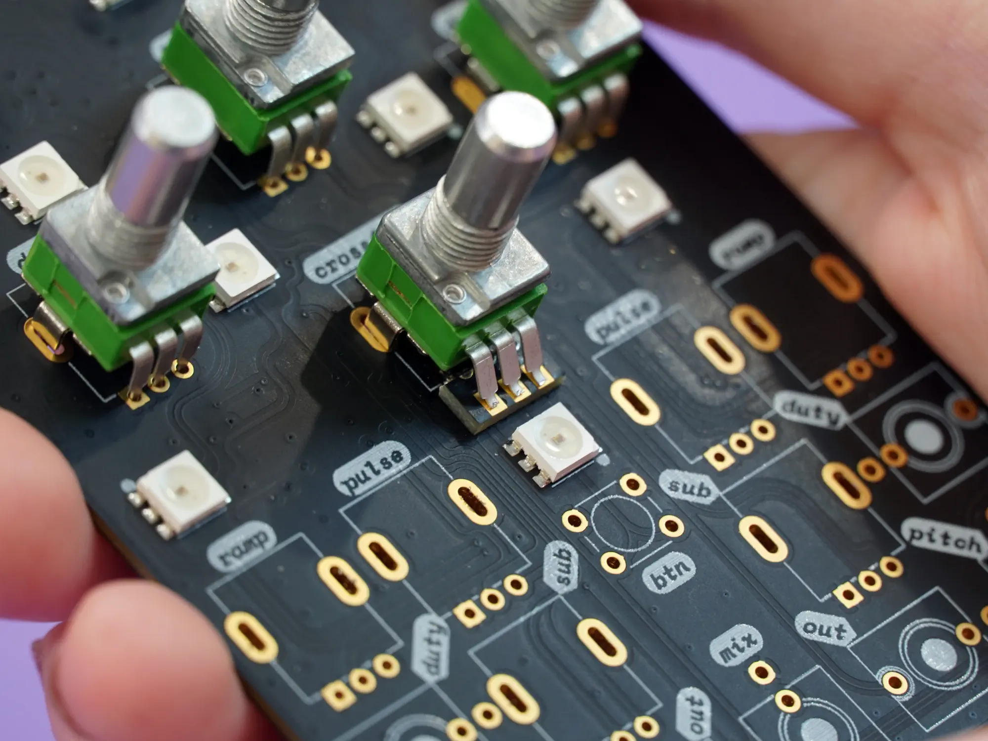
Next, take one of the 1/8" jacks and place it into the spot at the center bottom edge of the board labeled mix:
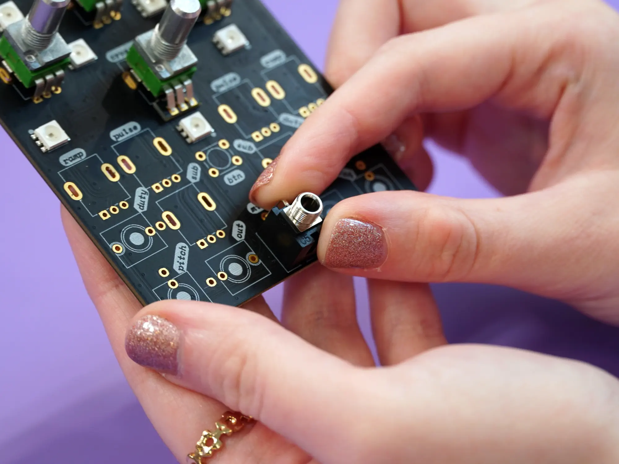
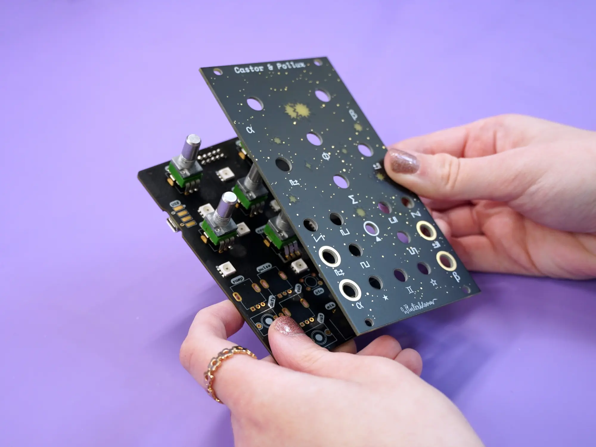
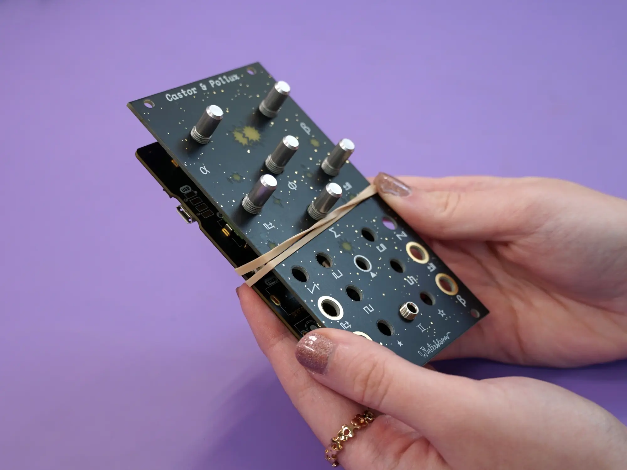
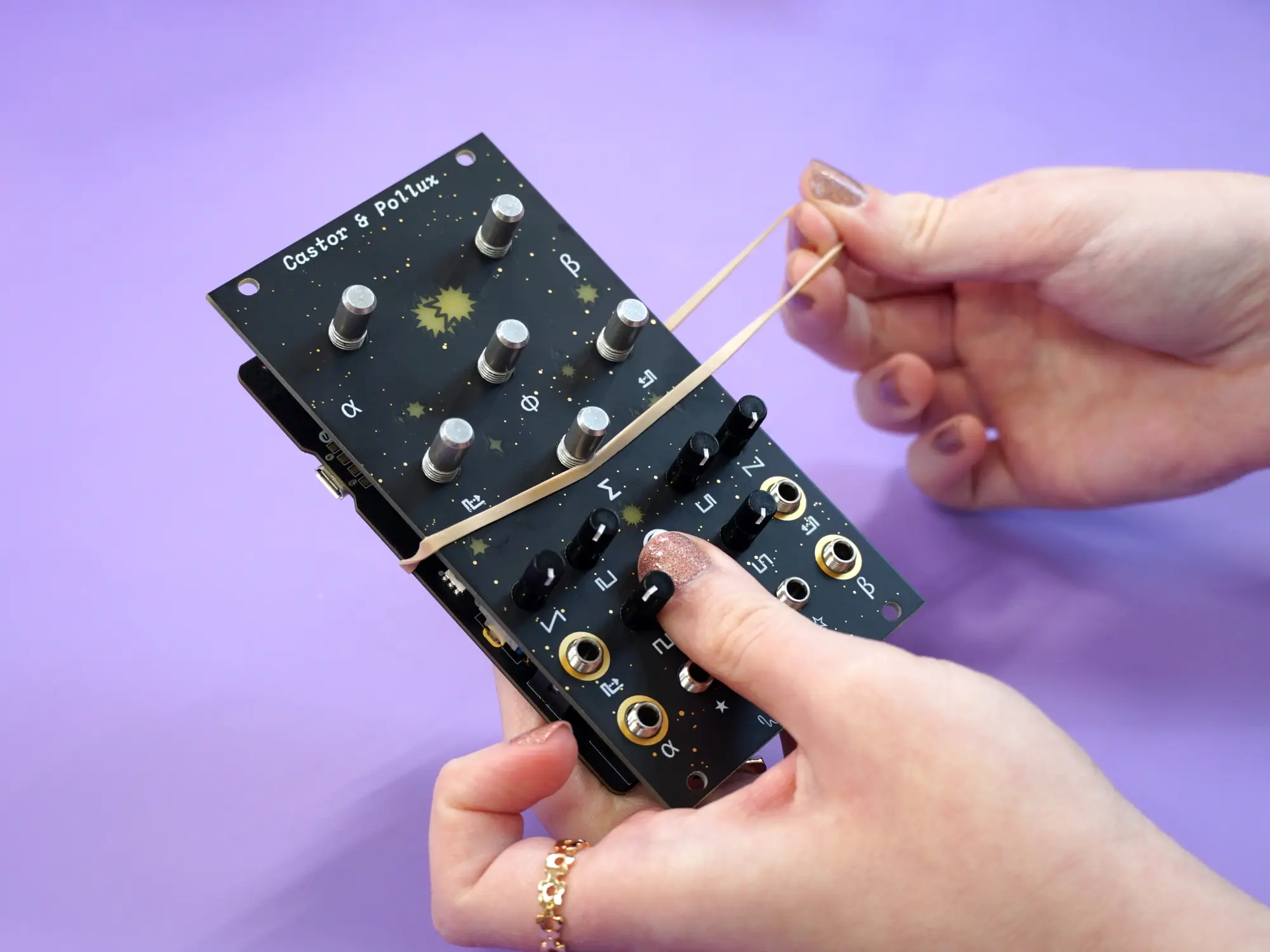
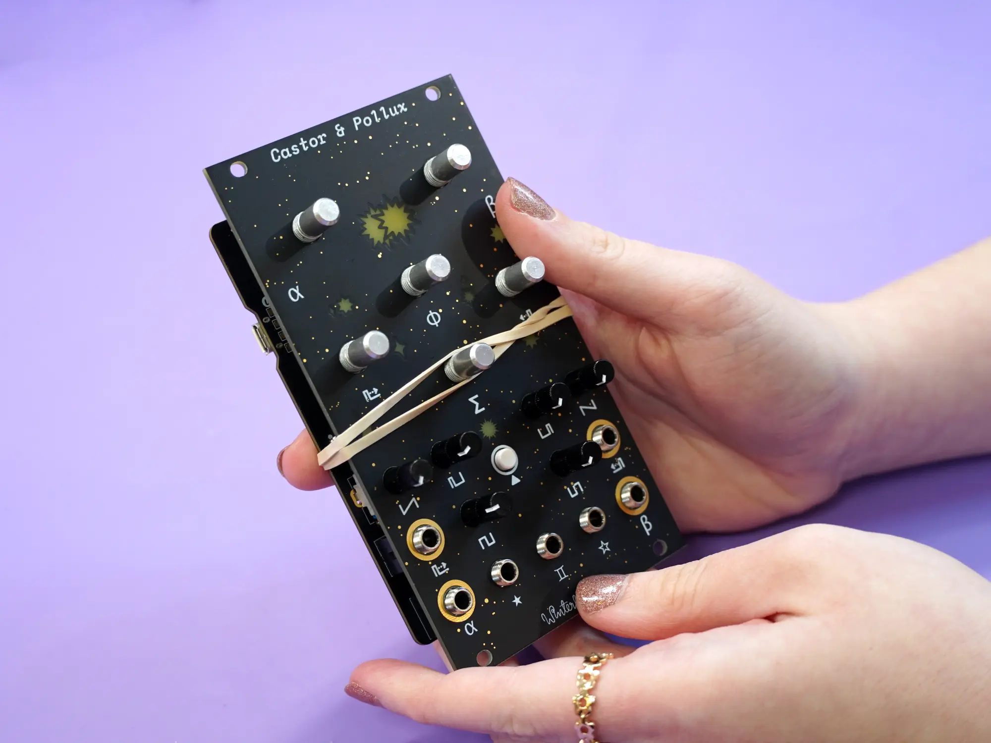
Next, carefully place the faceplate onto the front of the module. Make sure all of the pots and the jack are aligned and resting in their respective holes.
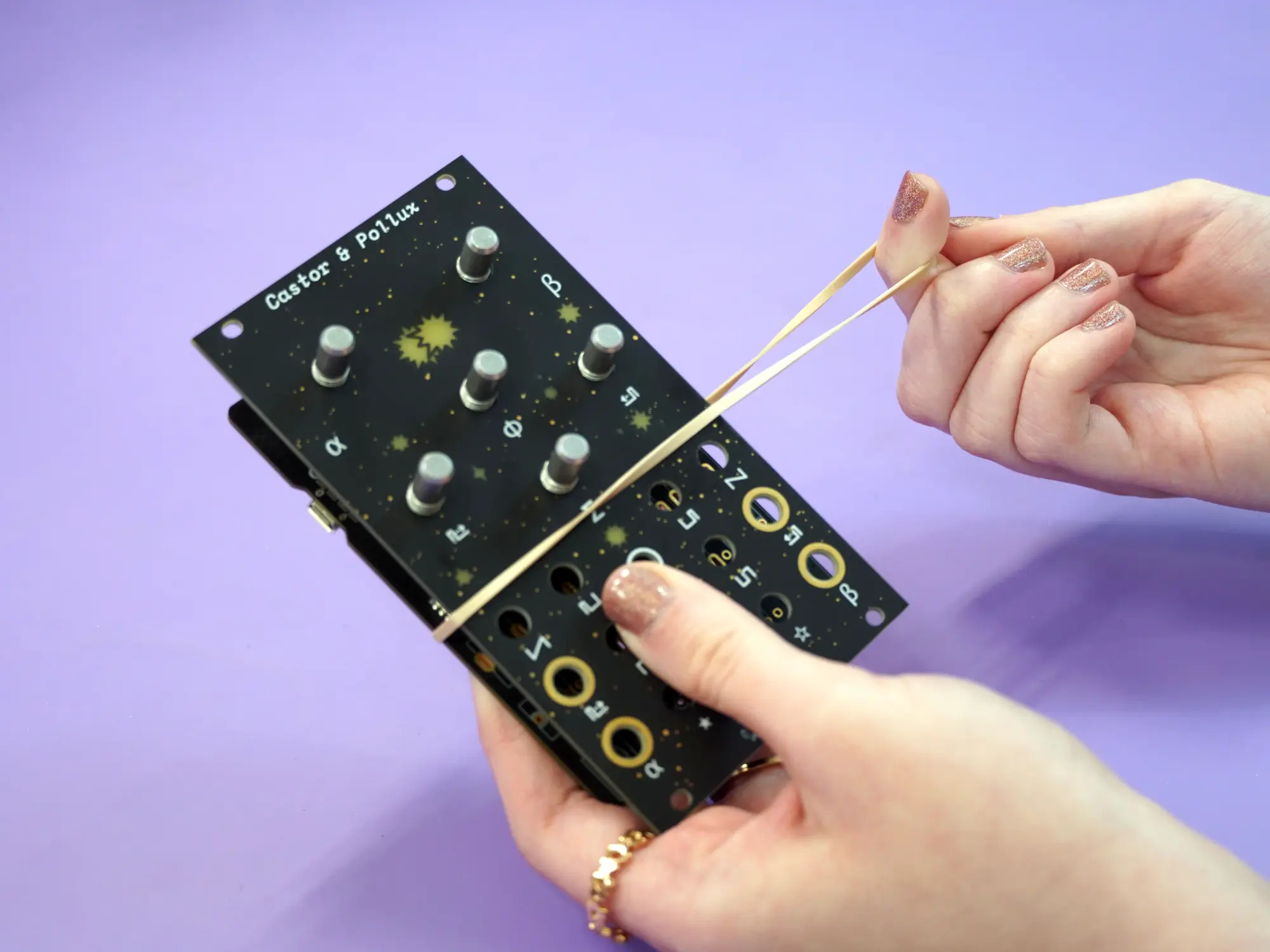
Take one of the rubber bands and wrap it around the board and faceplate twice to hold the faceplate in place during the next few steps.
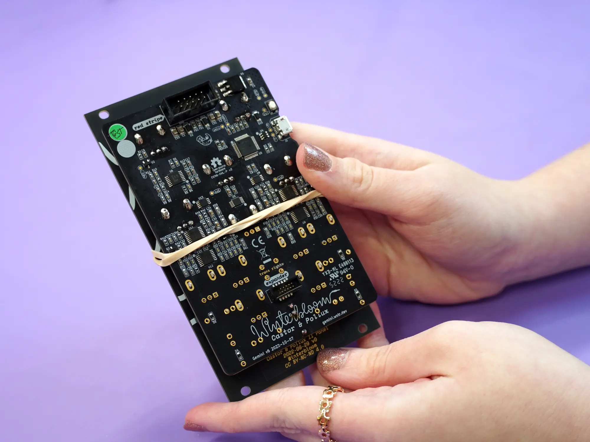
Flip the whole thing upside-down and solder the pots and jack in place.
Warning
Take extra care not to hit any of the surface mount components with your iron.
Next, flip the assembly rightside-up and remove the rubber bands and faceplate.

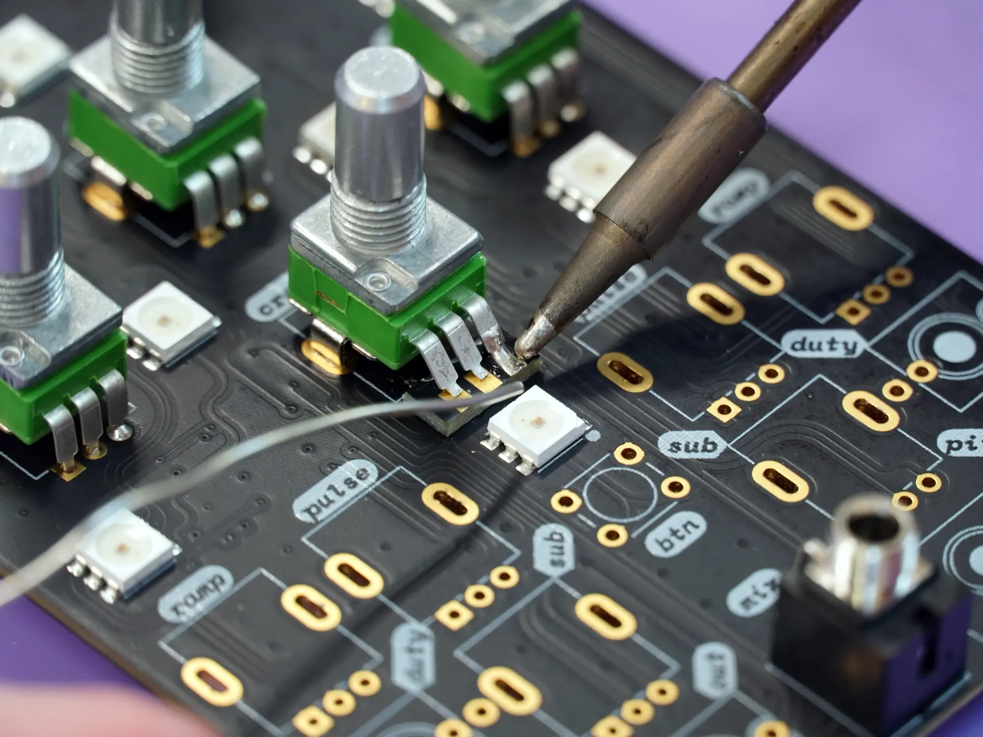
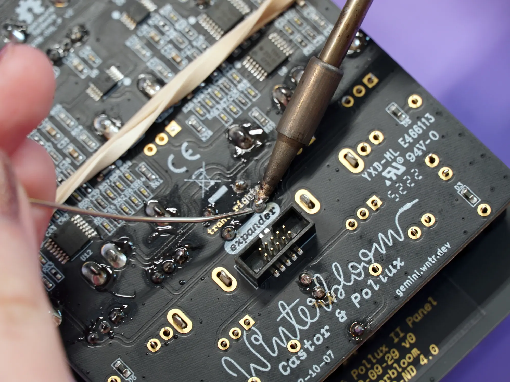
Finally, solder the legs of the modified pot to the pads on the board. Take care not to accidentally bridge the legs together. If you find that the legs are misaligned, you can flip the board back over and melt the solder on the mounting legs and twist it back into alignment.
Tactile switch#
Next up is the tactile switch and its cap.
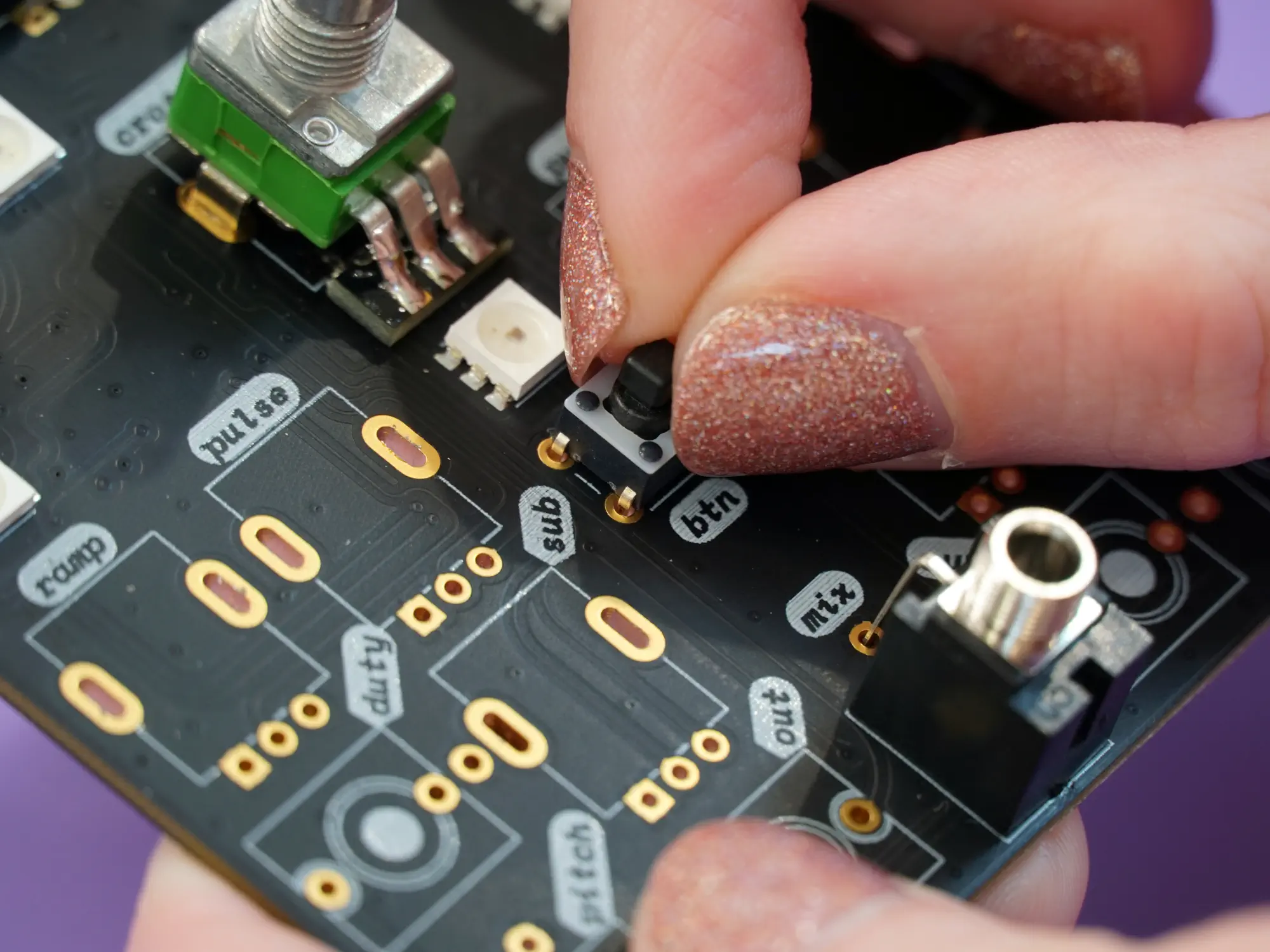
Place the tactile switch on the spot labeled btn on the mainboard. Make sure it's fully inserted against the board.
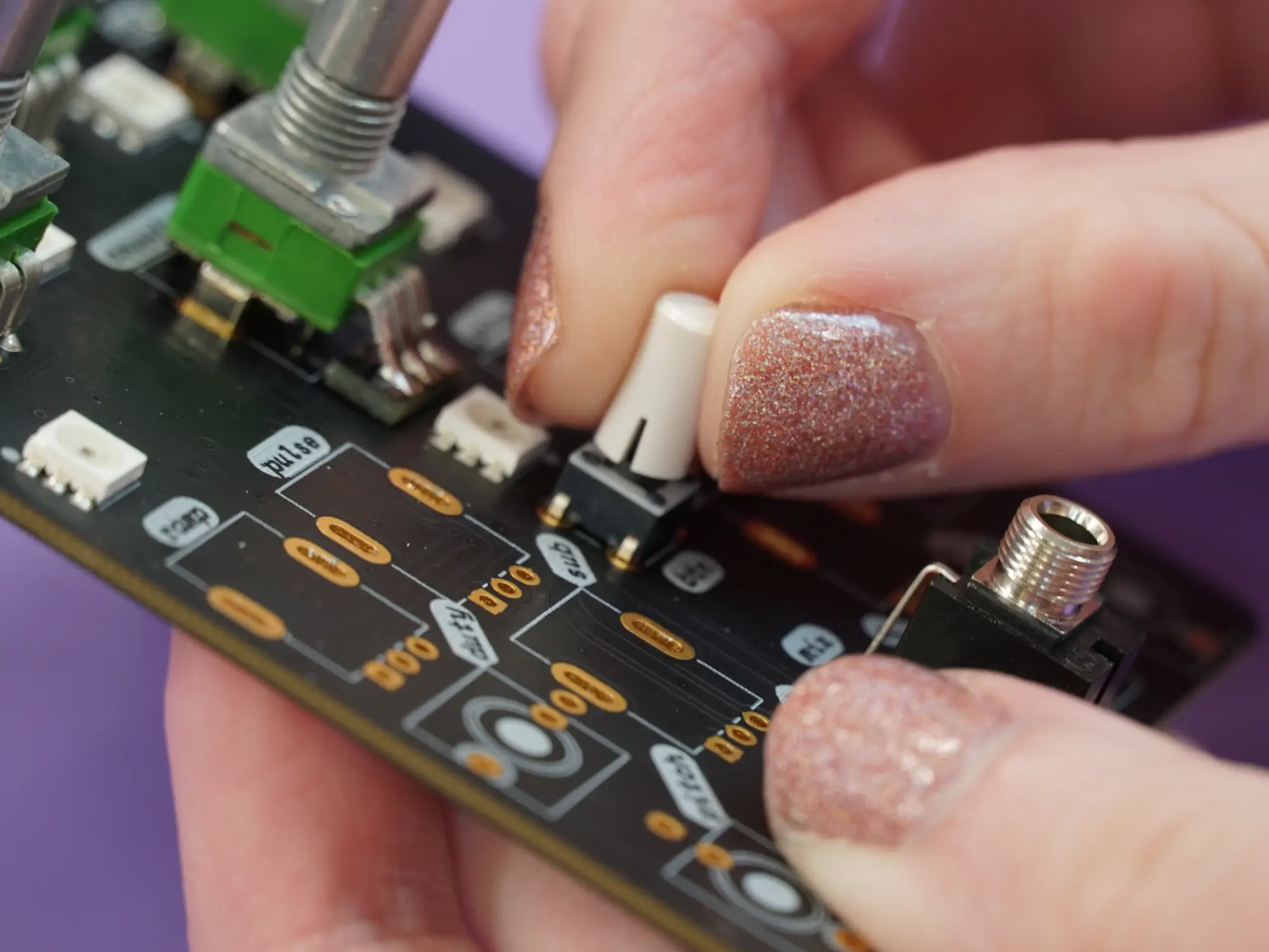
Next, place the cap on top of the tactile switch and press in firmly to completely seat it on the switch.
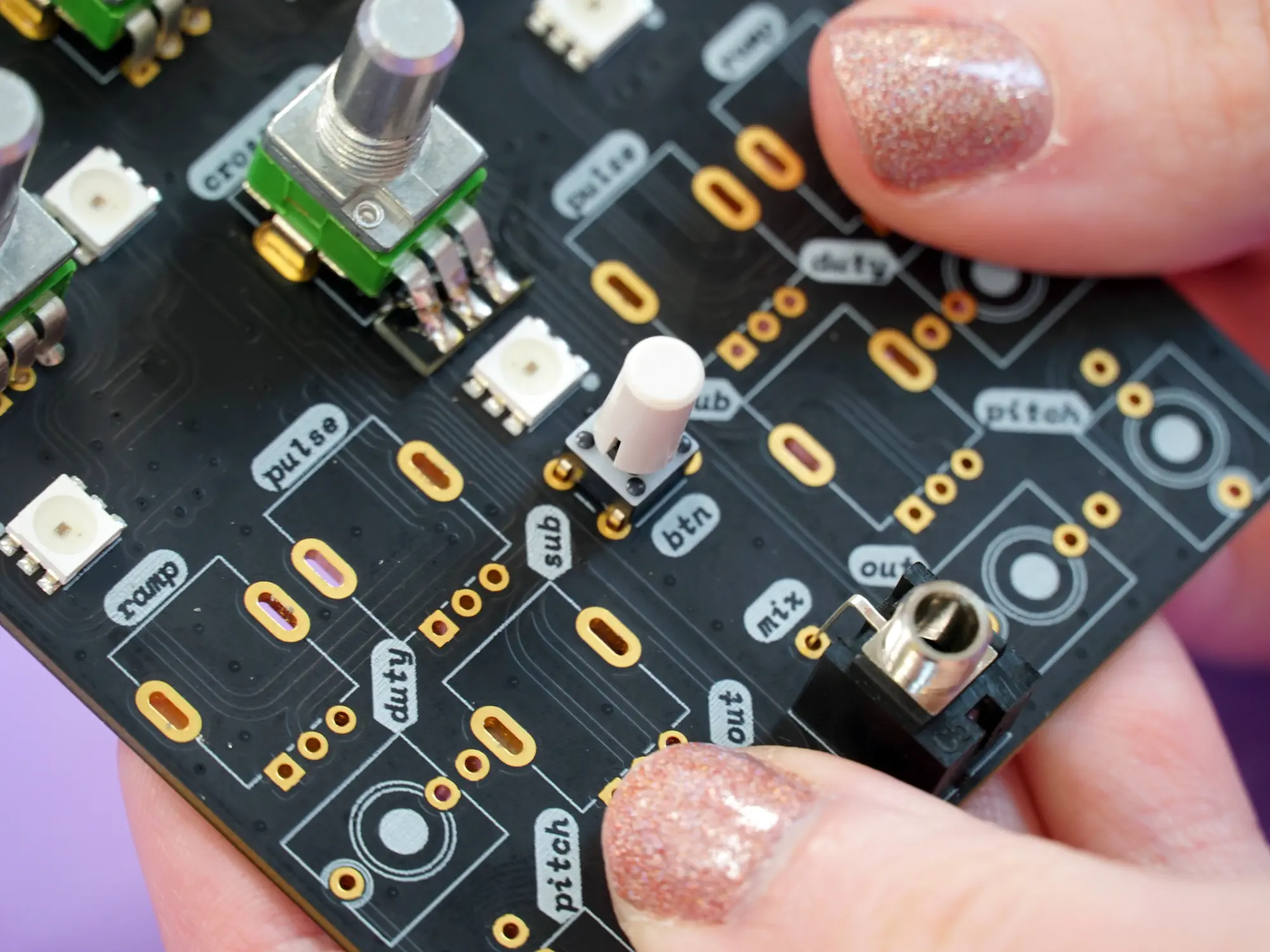
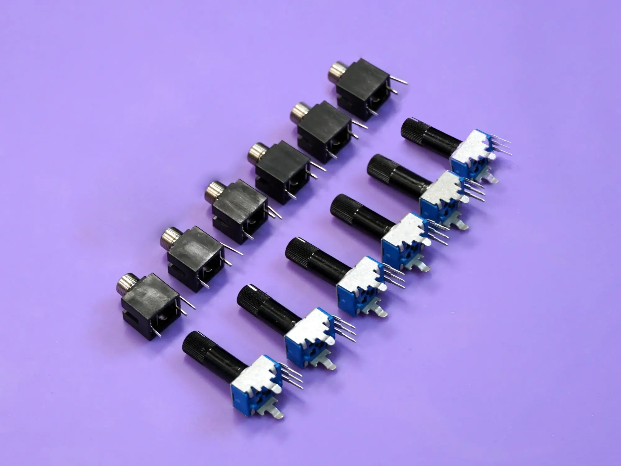
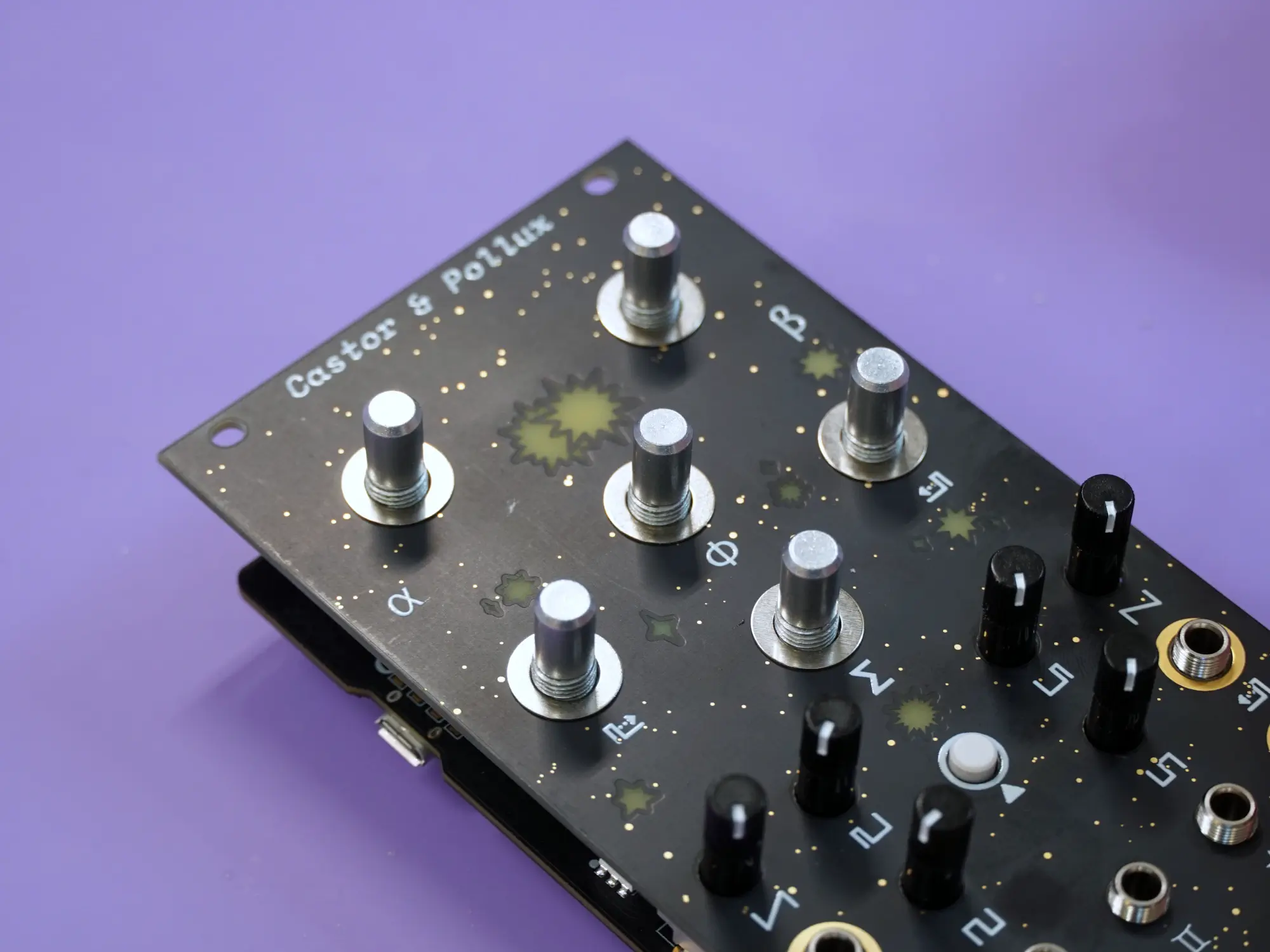
Jacks and trimpots#
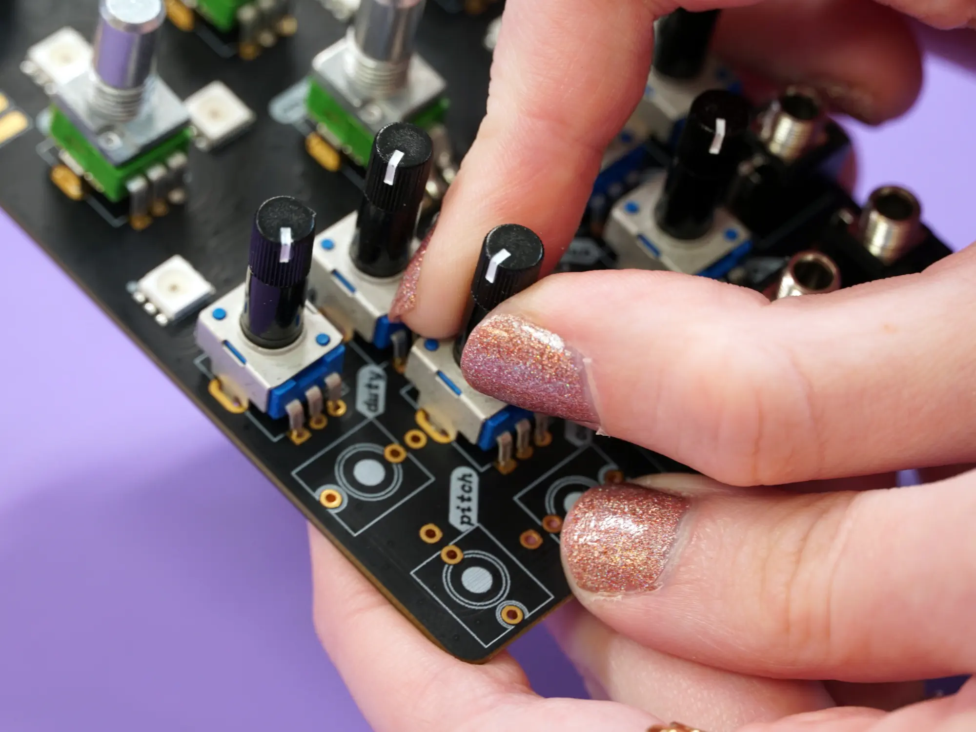
Next up is all six trimpots and six of the 1/8" jacks.
Start from the right side of the board and place the pots and jacks for ramp, pulse, duty, sub, pitch, and out.
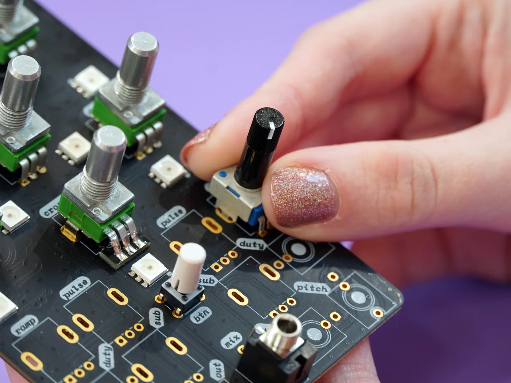
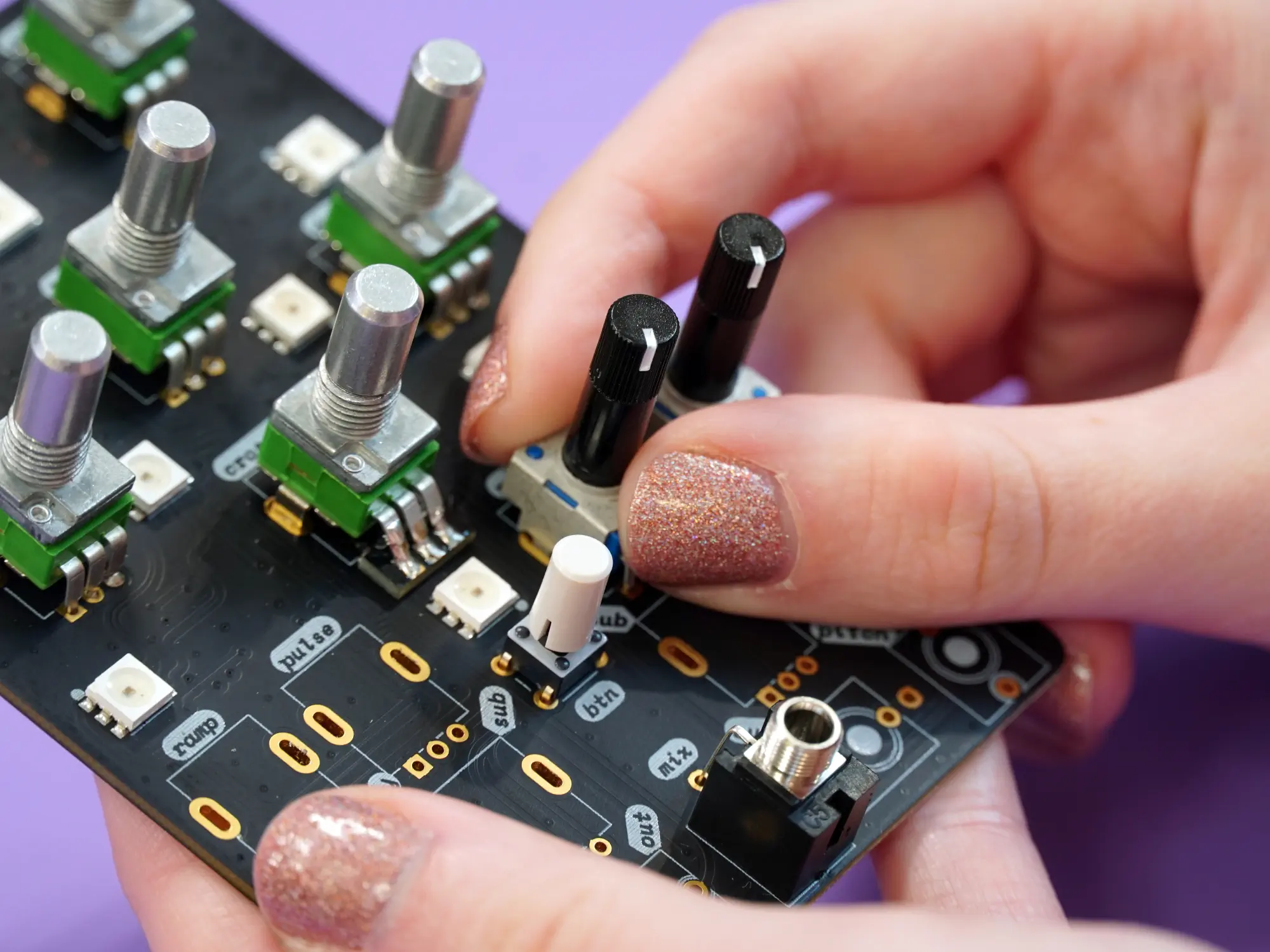
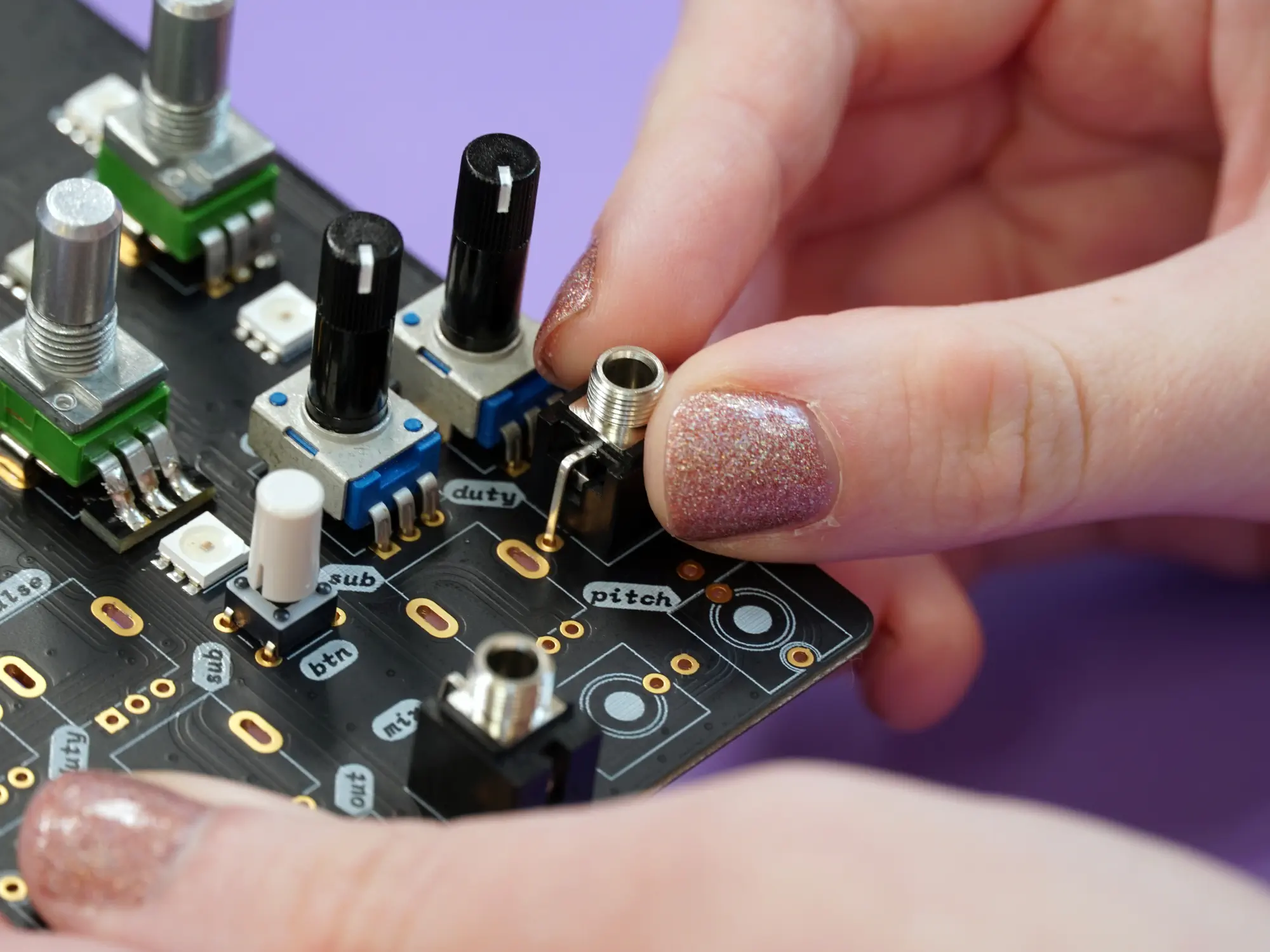
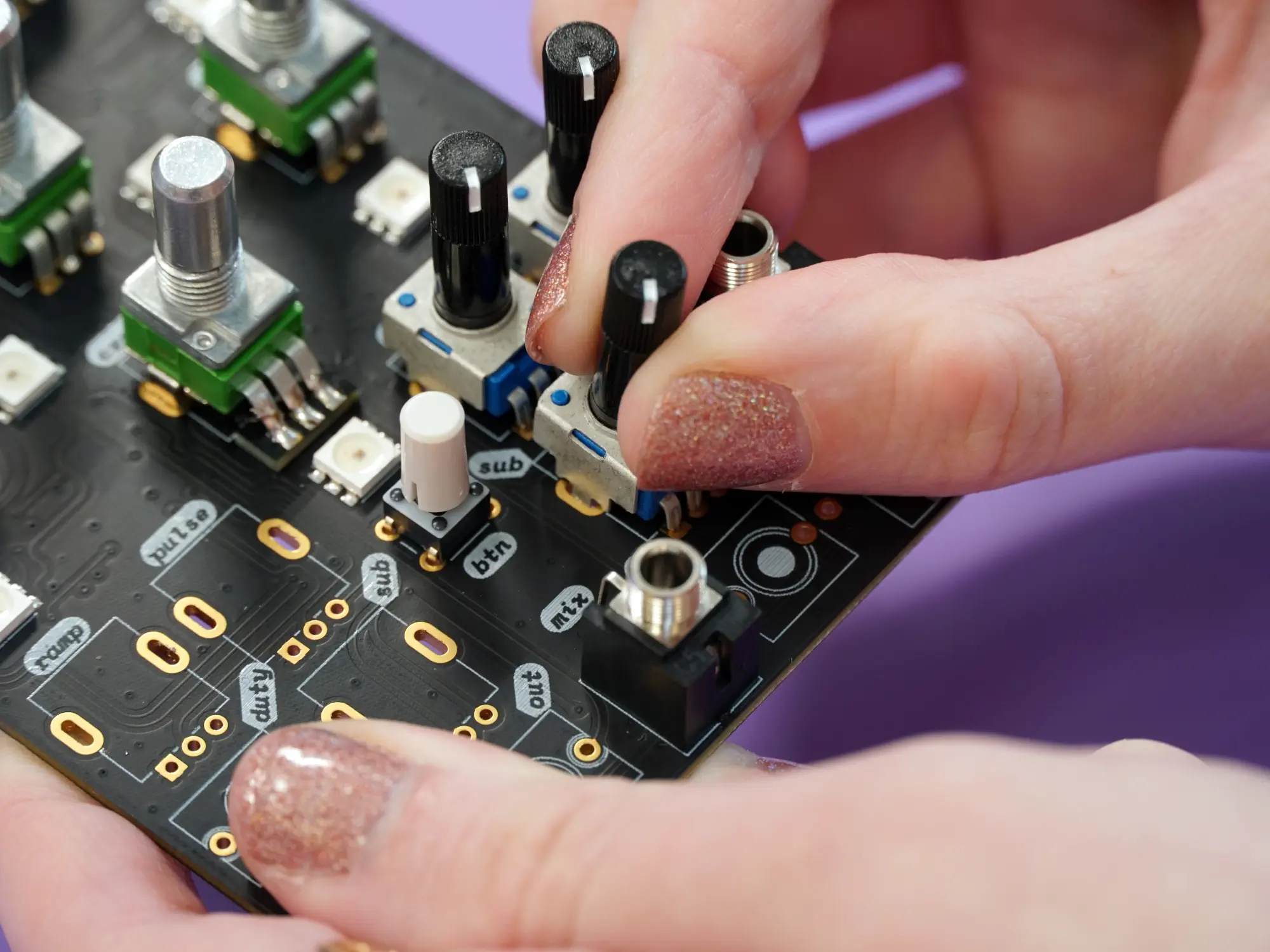
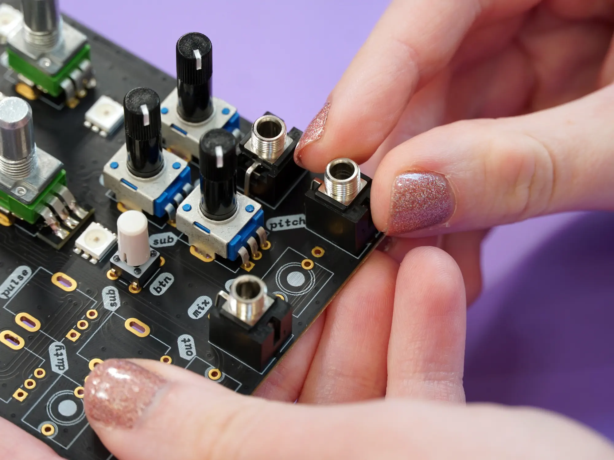
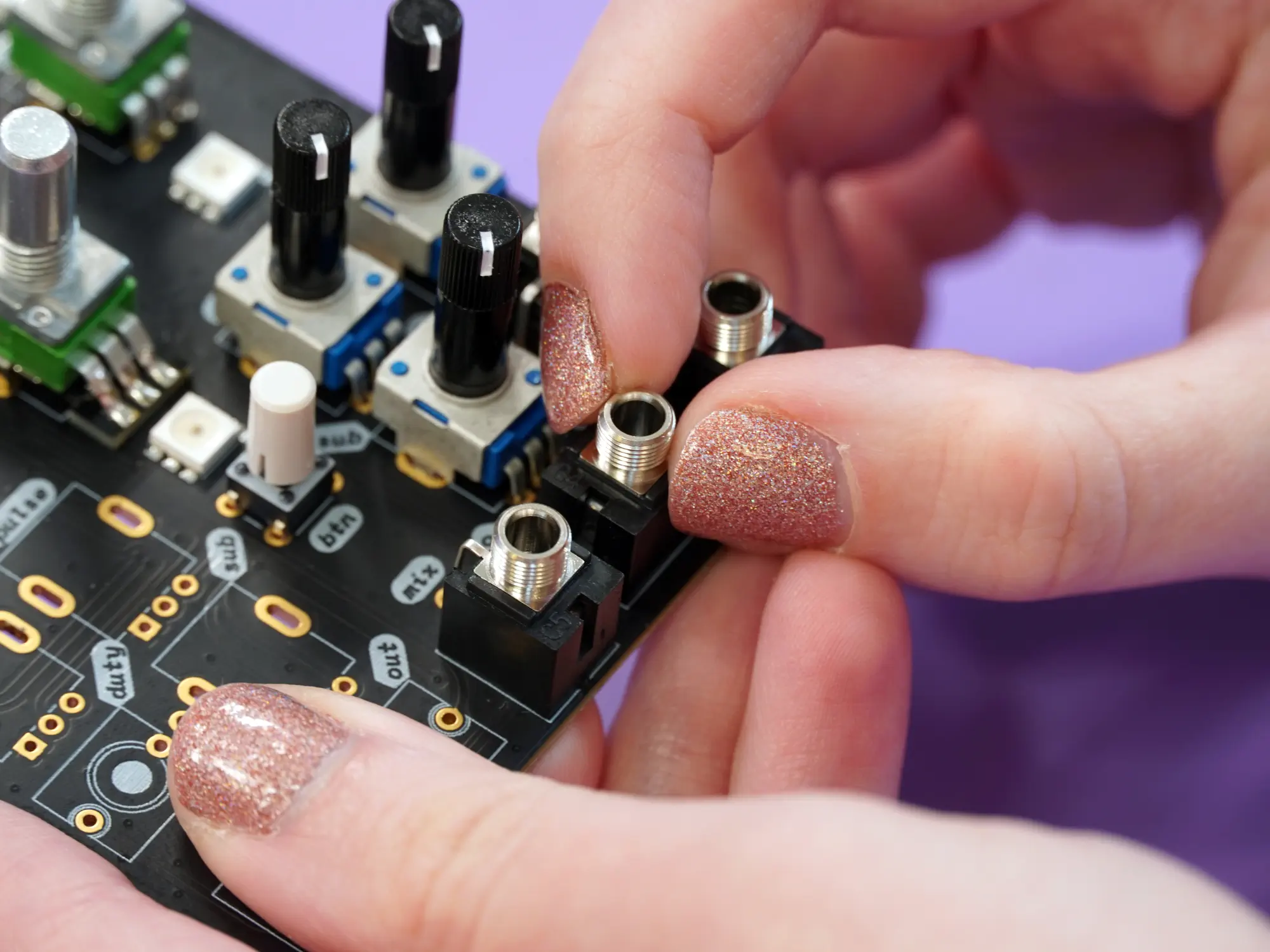
Continue on the left side with the pots and jacks for pulse, ramp, sub, duty, out, and pitch.
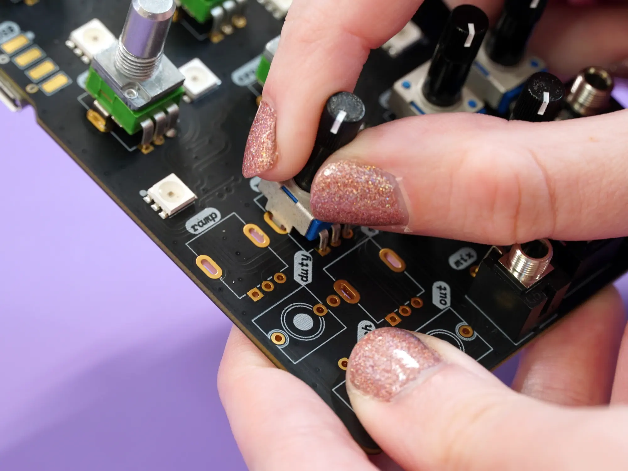
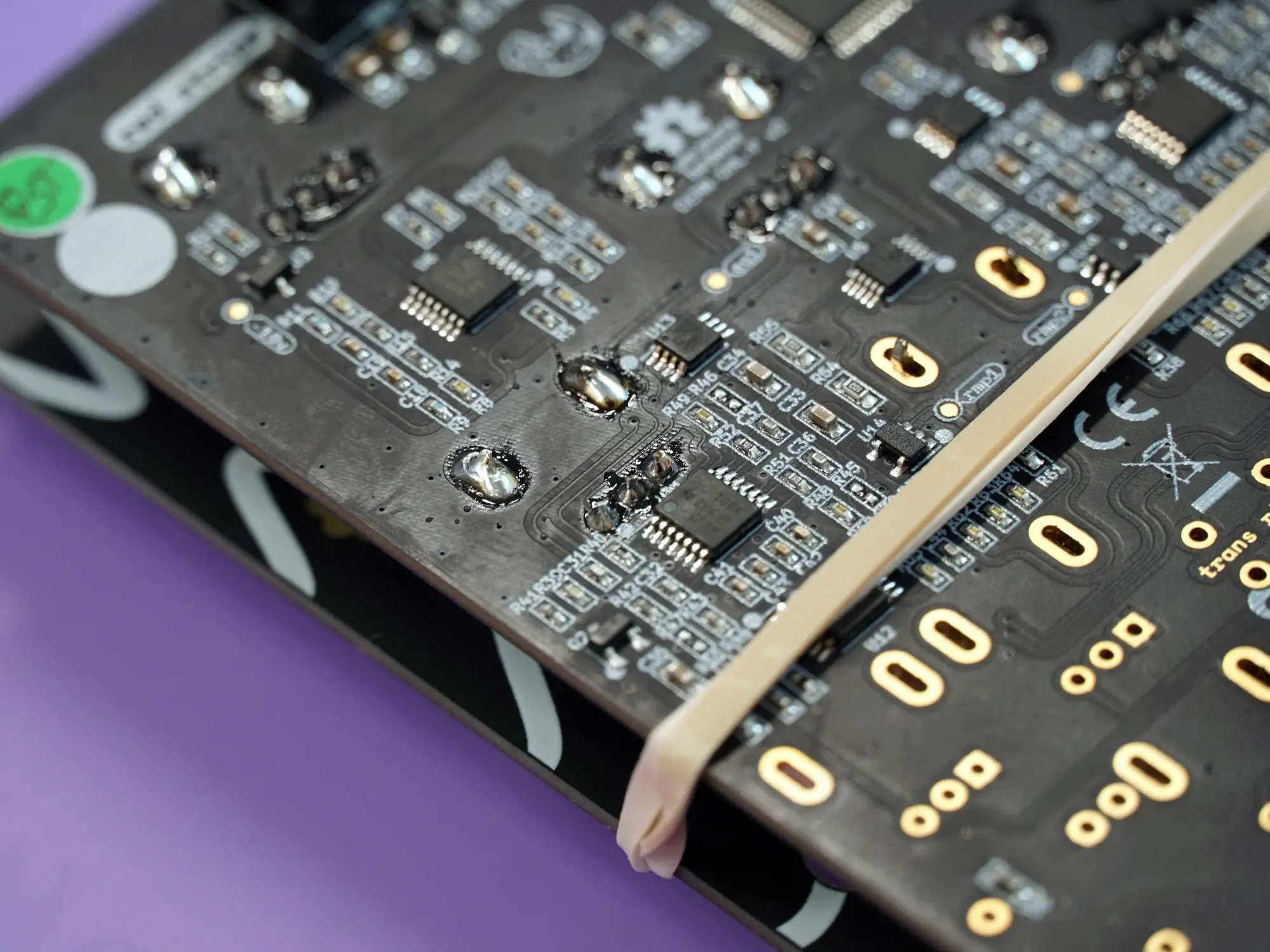
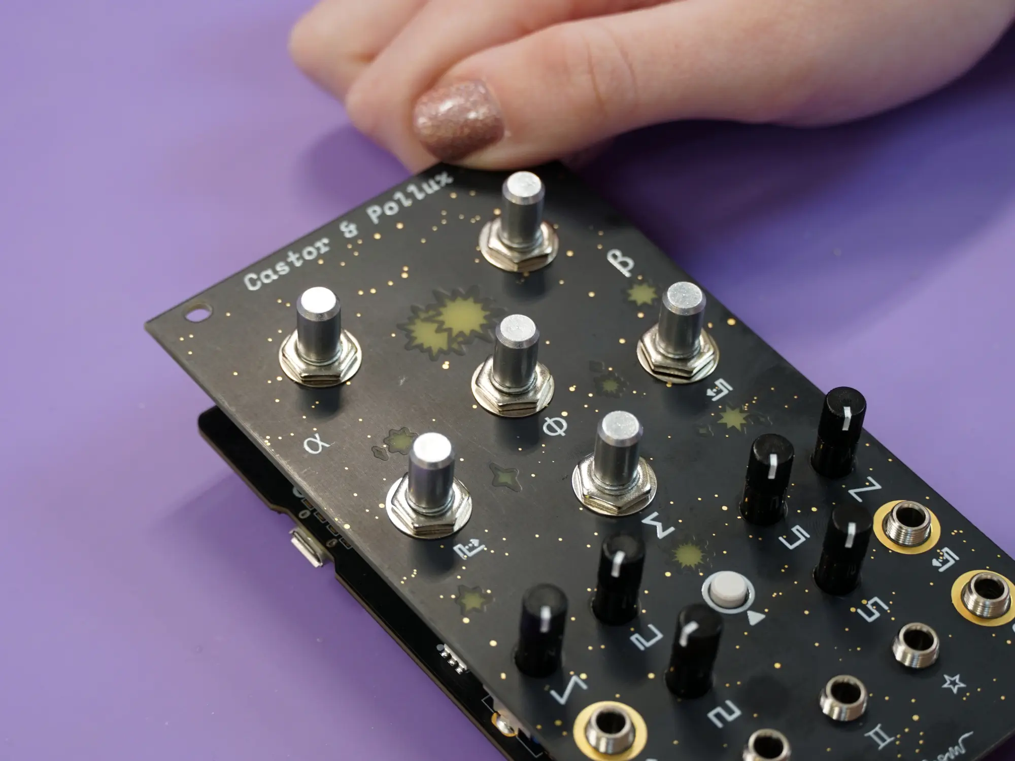
Next, place the faceplate and rubber band just as you did earlier.
Flip the module upside-down and solder the pots and jacks into place.
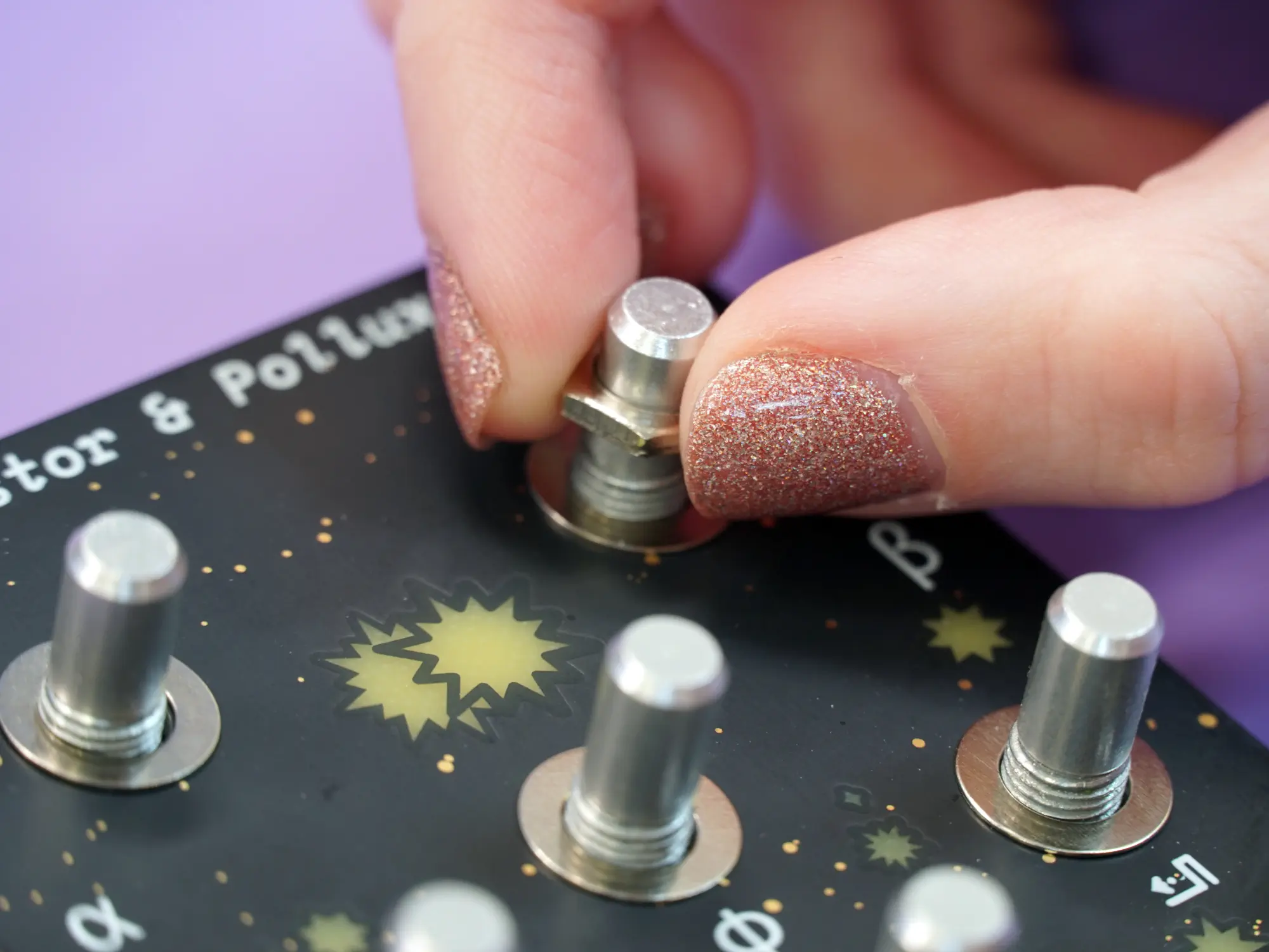
Nuts#
Now that everything is soldered in place the next step is to secure the faceplate using nuts. Start with the six larger nuts and washers for the 9mm pots.
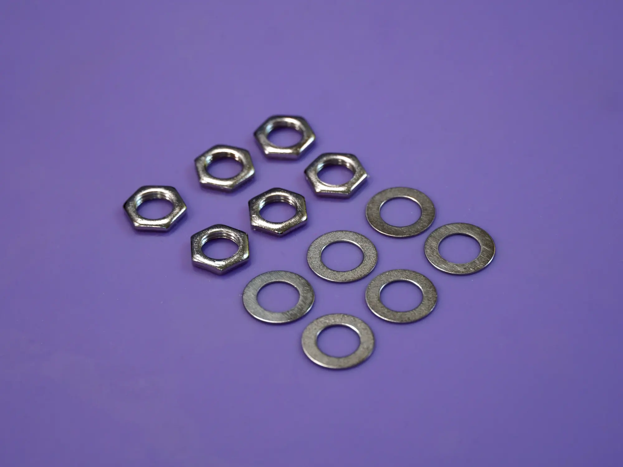
Place a washer on the shaft of each of the six 9mm pots.
With the washers in place, place the nuts onto the shafts and tighten them in place.
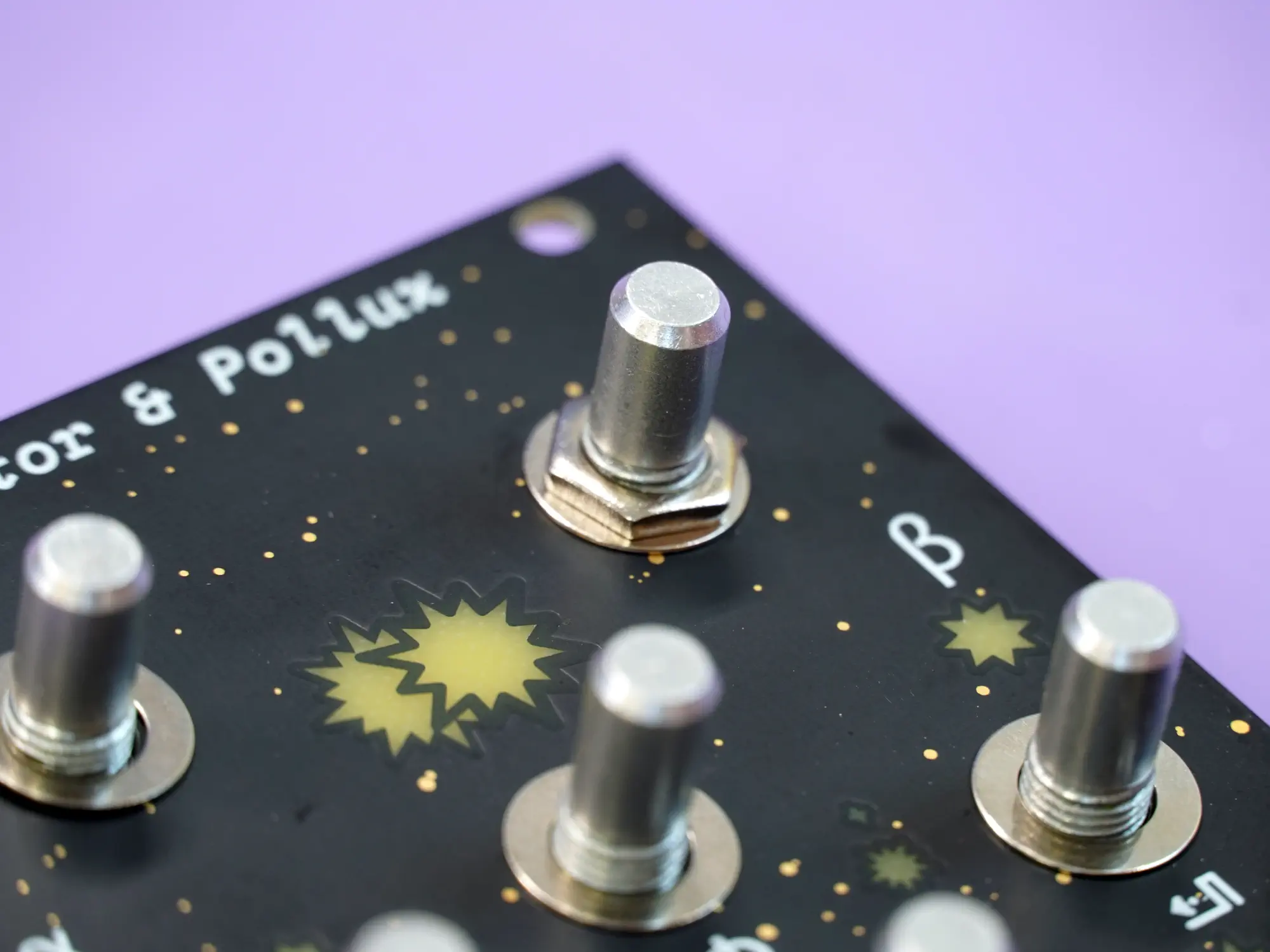
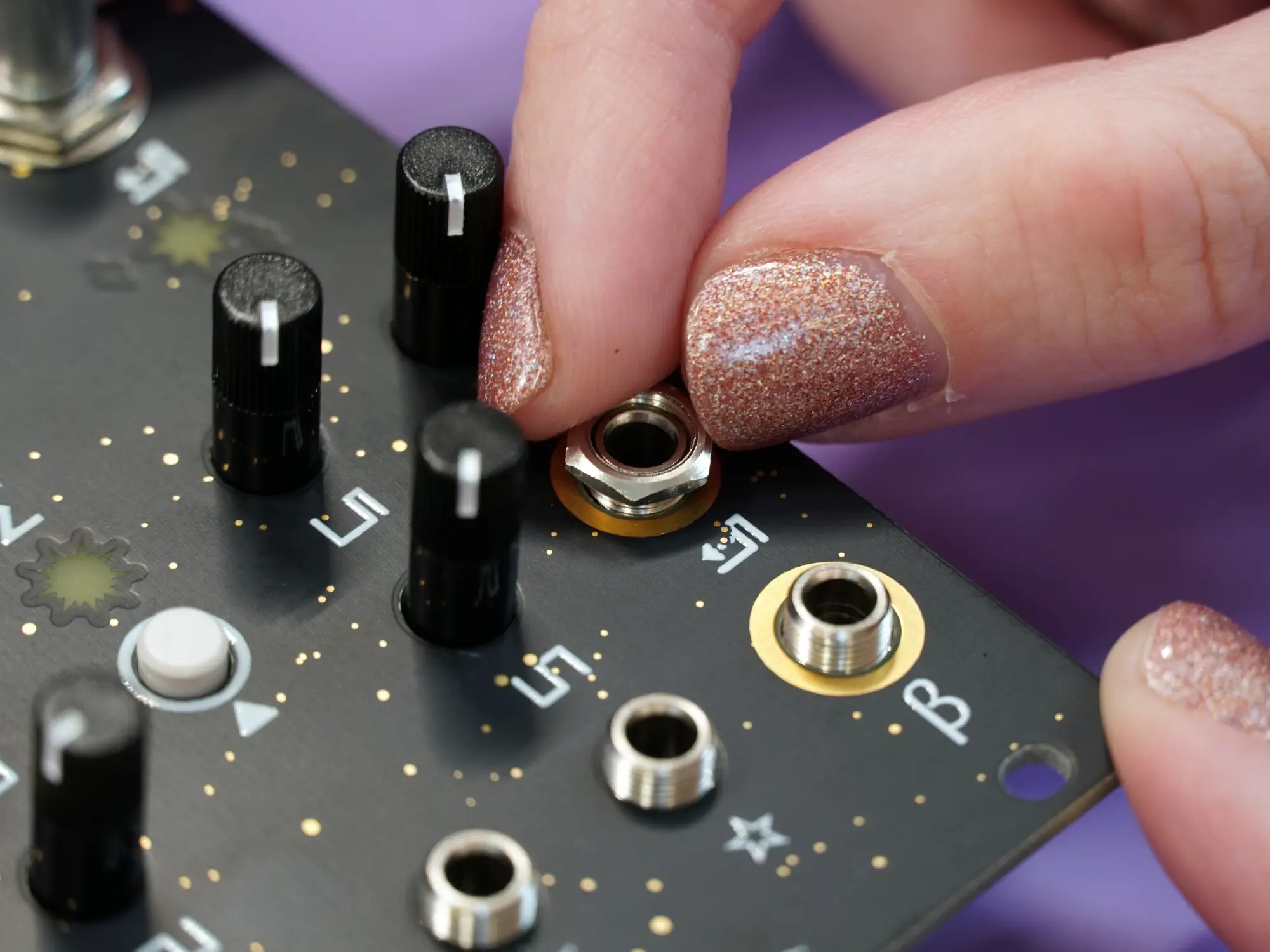
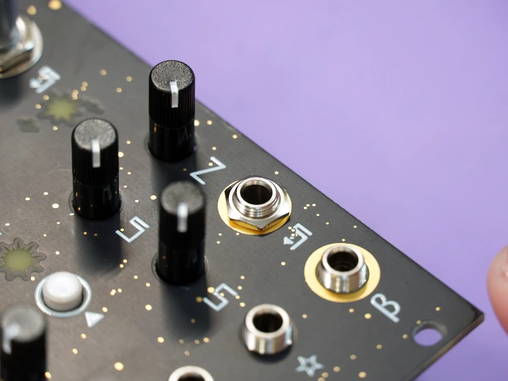
Next up is the seven hex nuts for the 1/8 jacks.
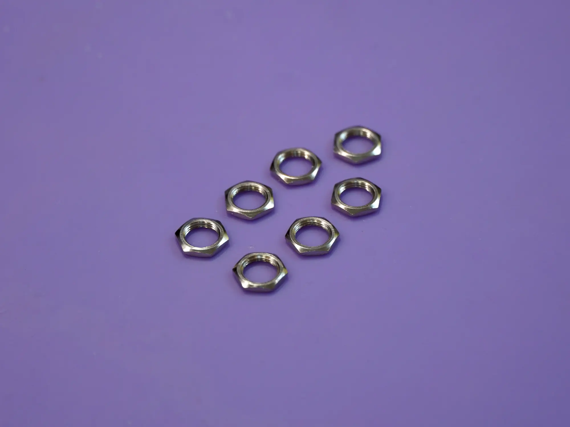
Place the nuts on each jack and tighten them in place.
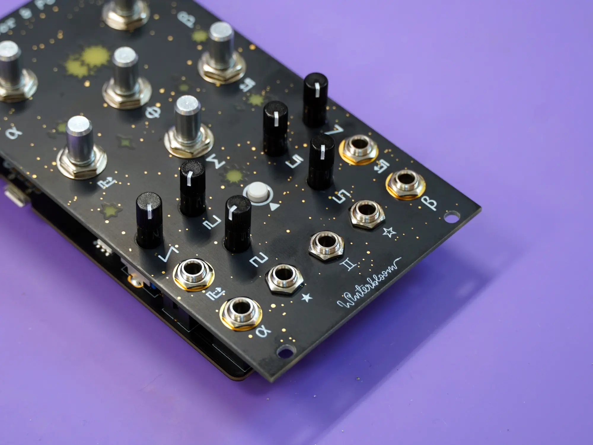
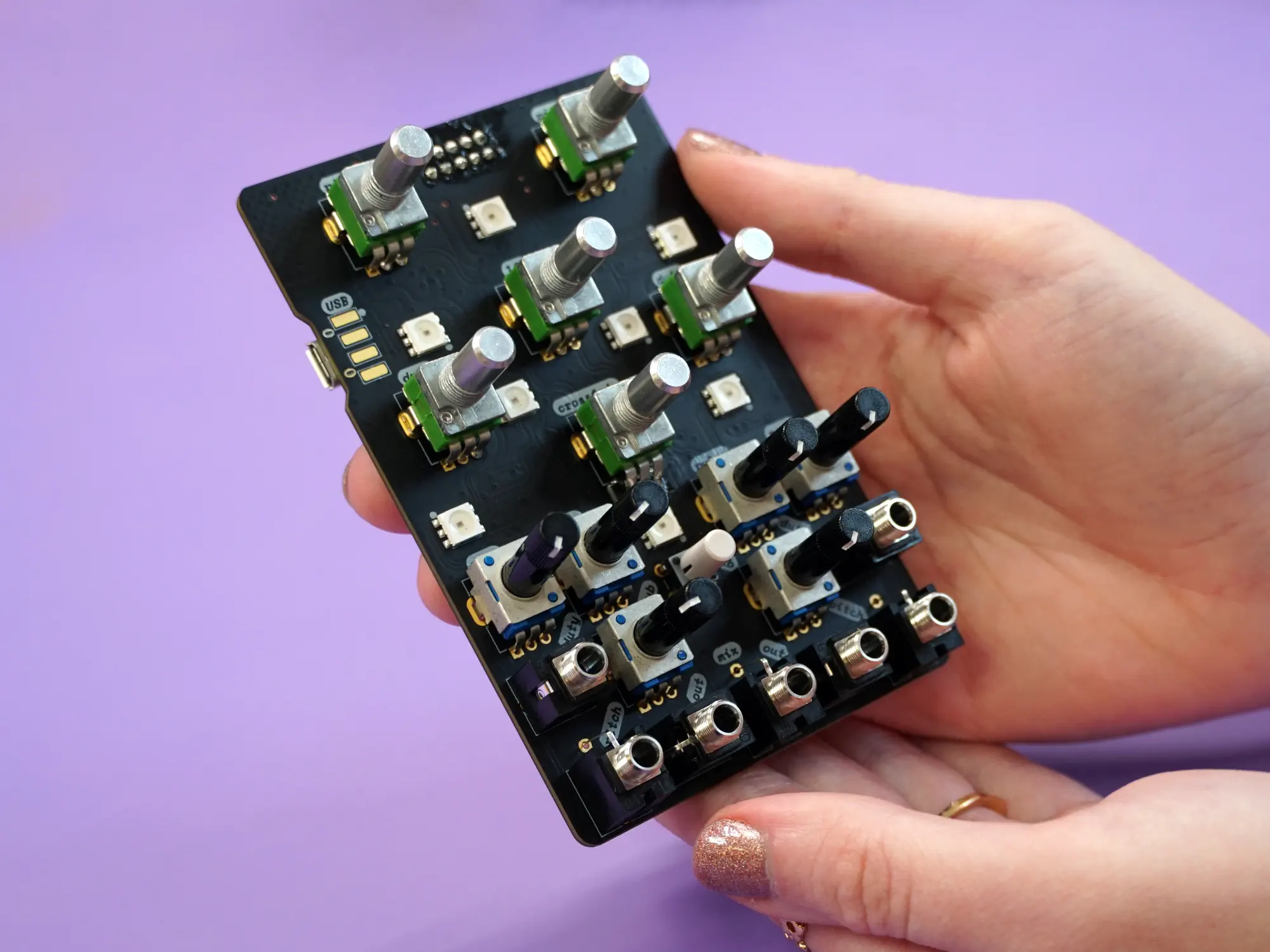
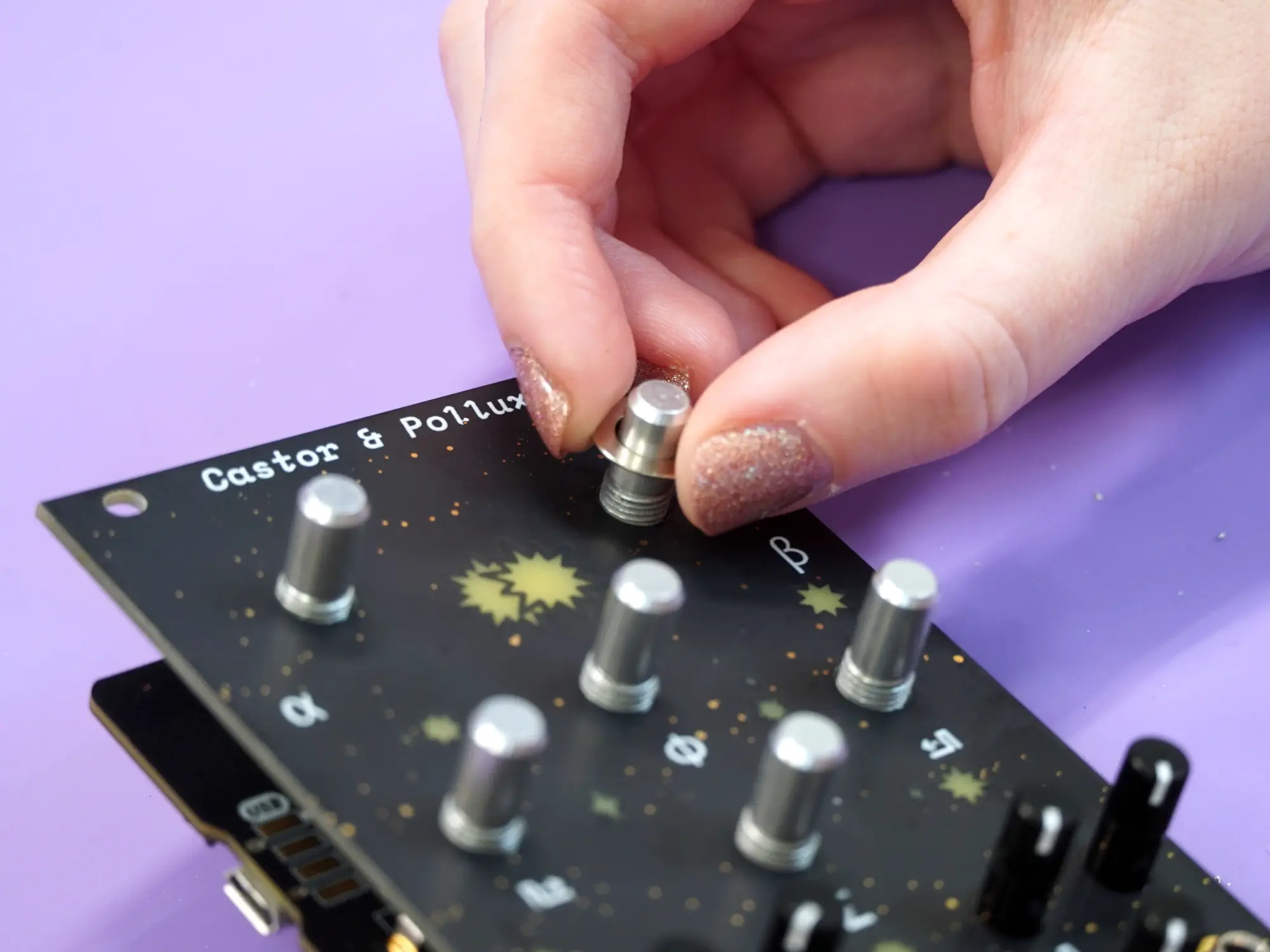
Knobs#
The final step for the main module is attaching the six knobs.
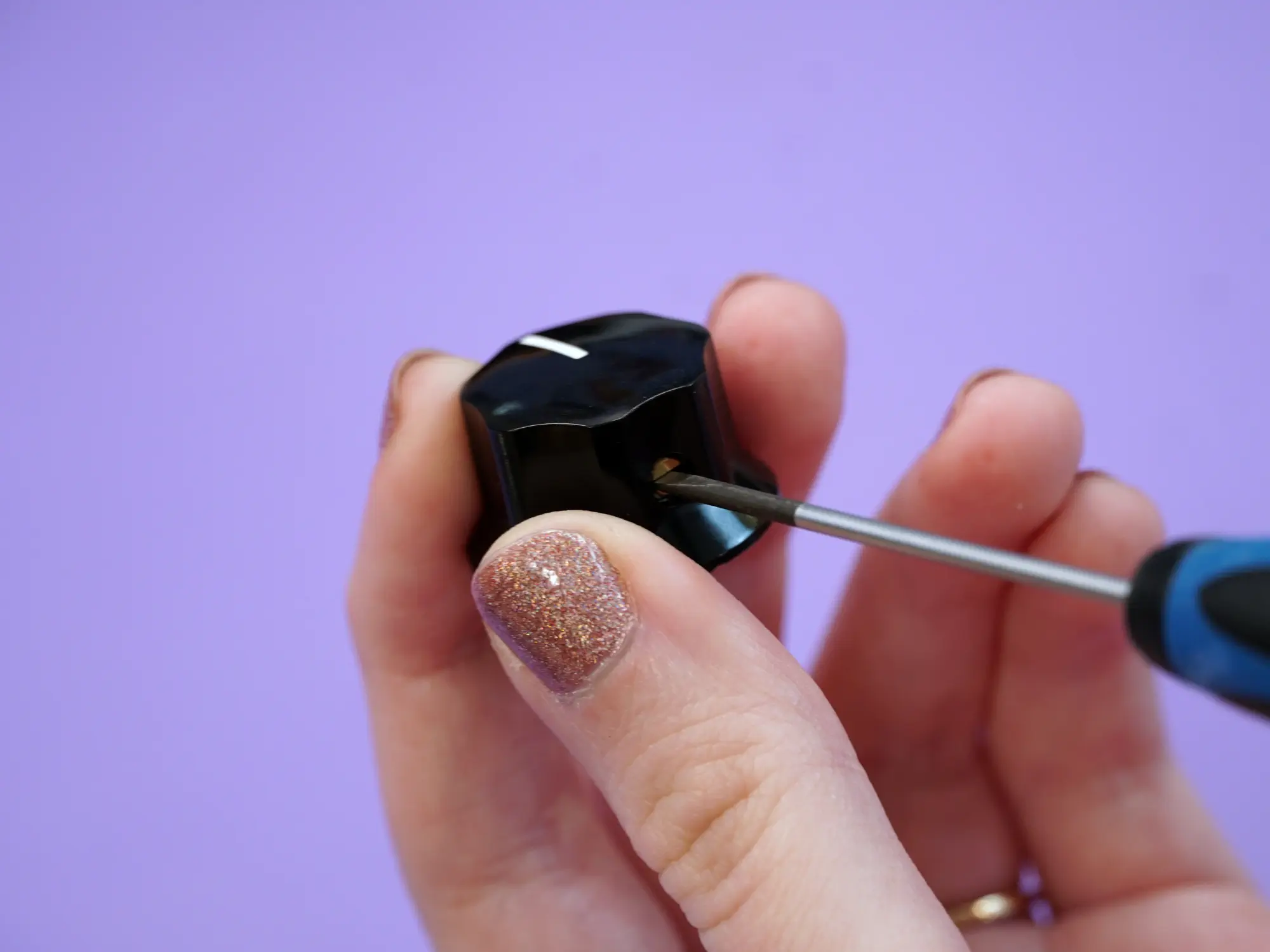
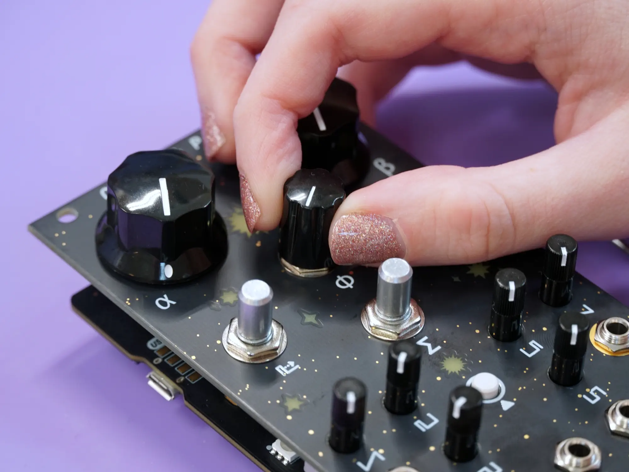
Start by loosening the set screw on each of the knobs using a small flat head screwdriver.
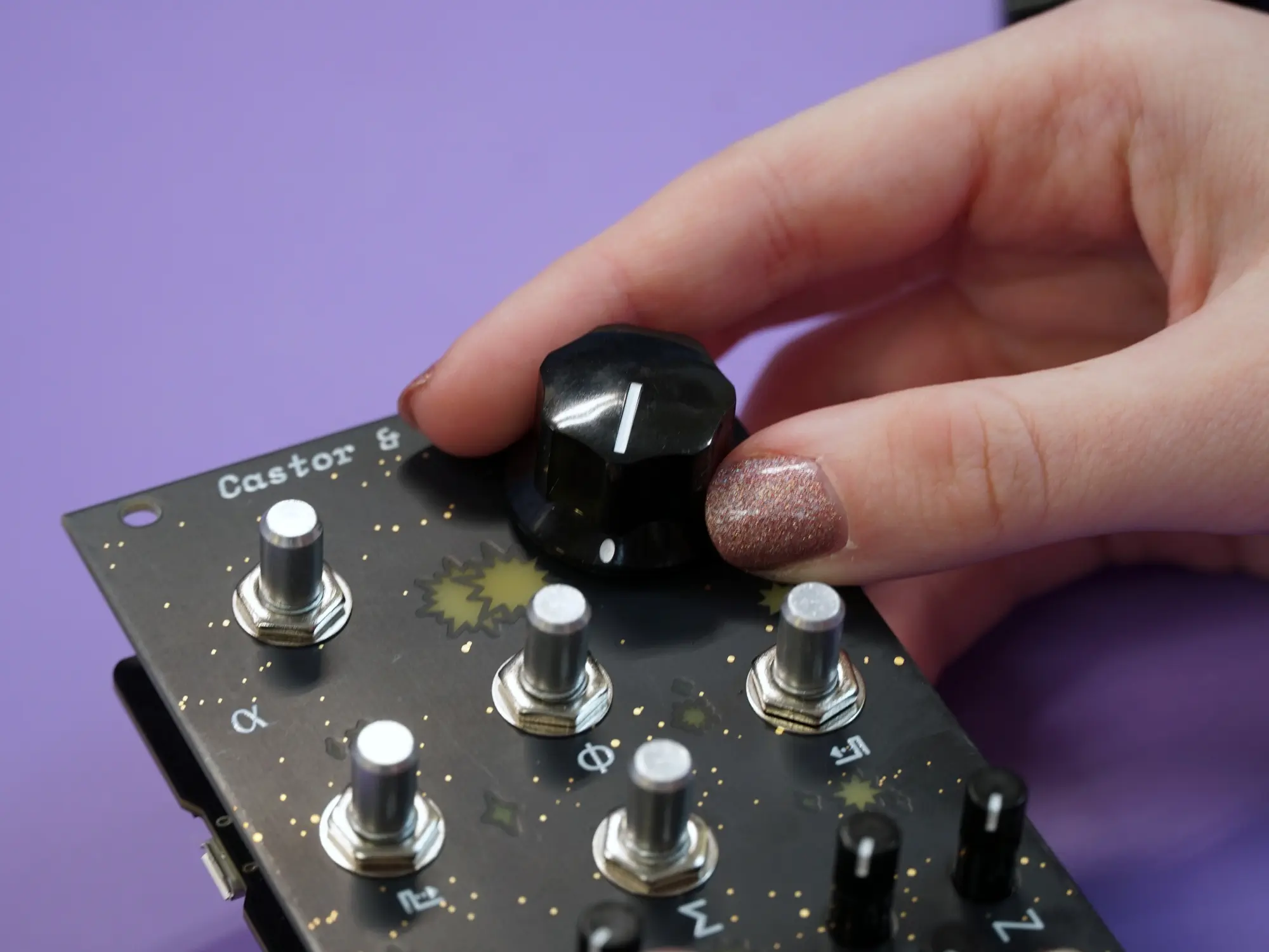
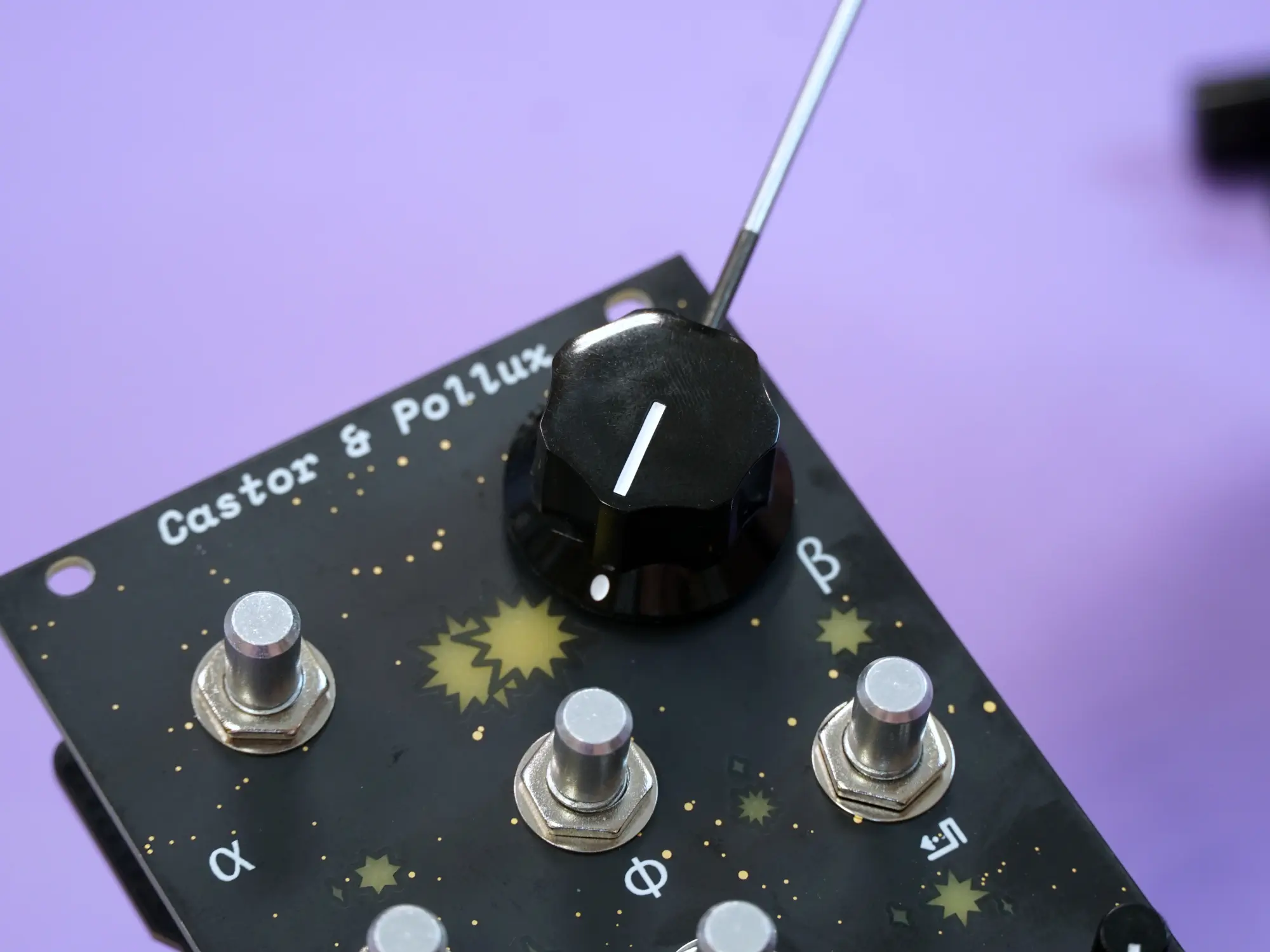
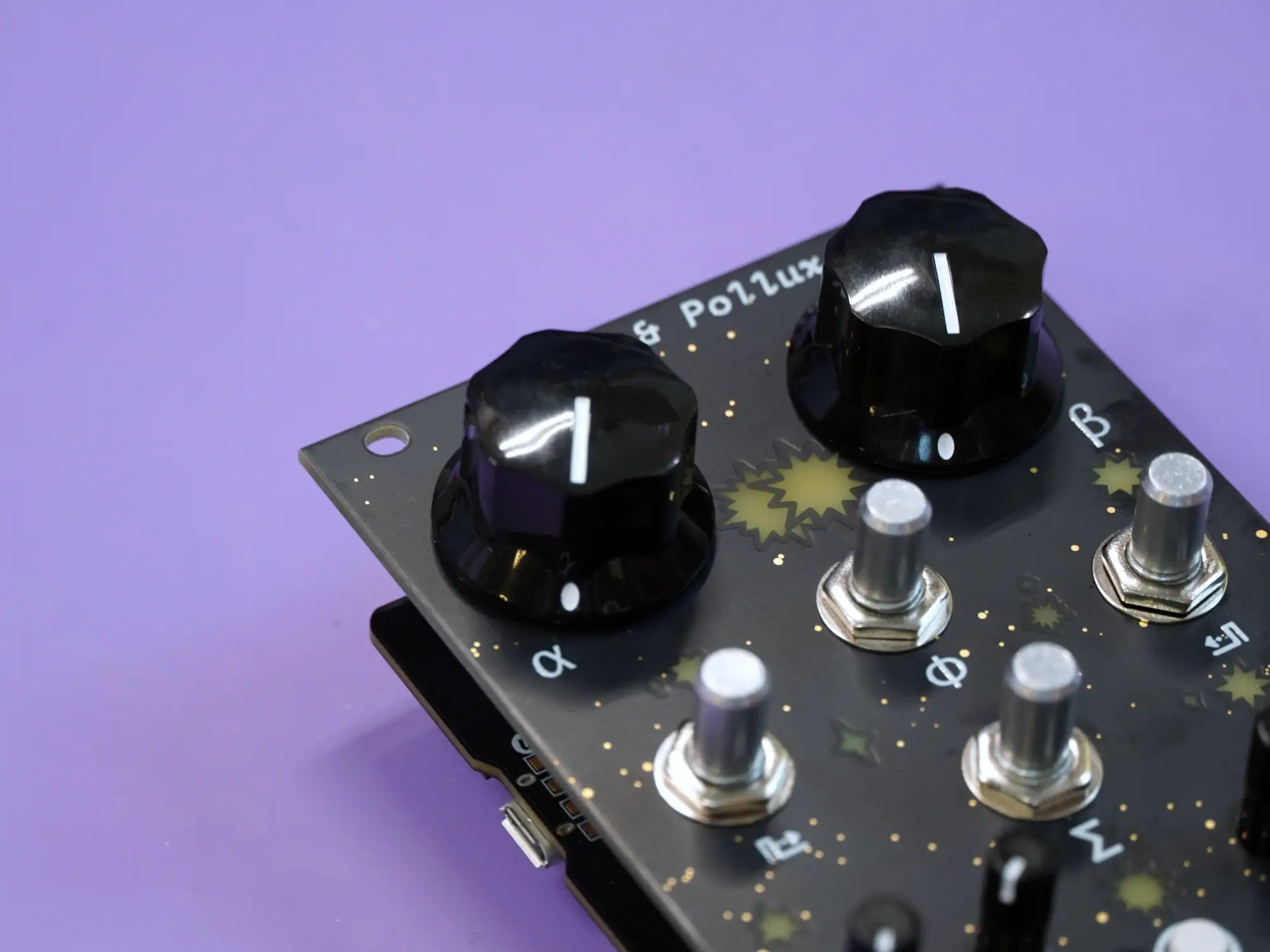
Next, turn all of the potentiometers fully counterclockwise. Place the two large knobs on the top two shafts with the indicator line at the 7 o' clock position. Tighten the set screws to secure the knobs in place.
Repeat the same process for the four smaller knobs.
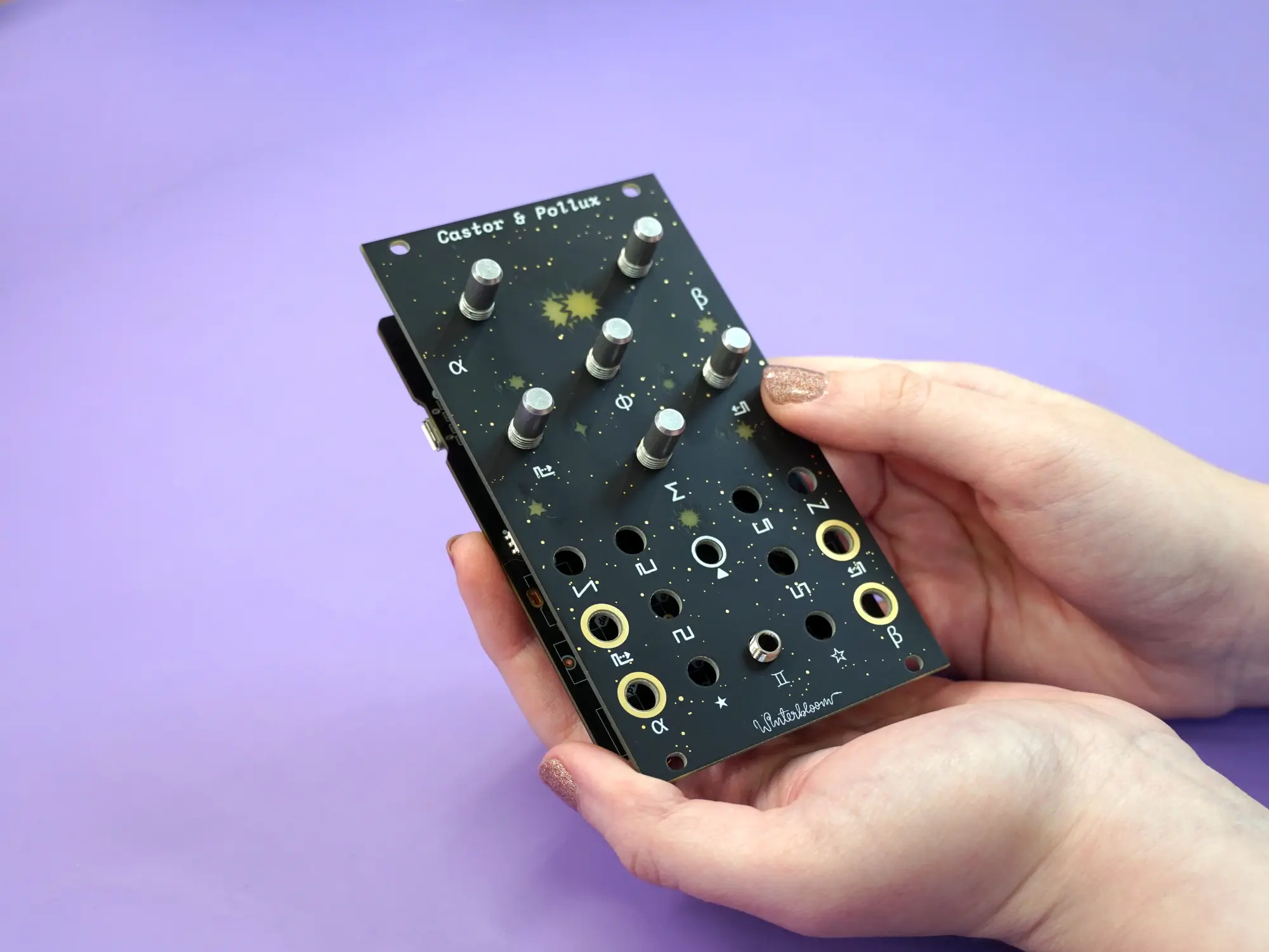
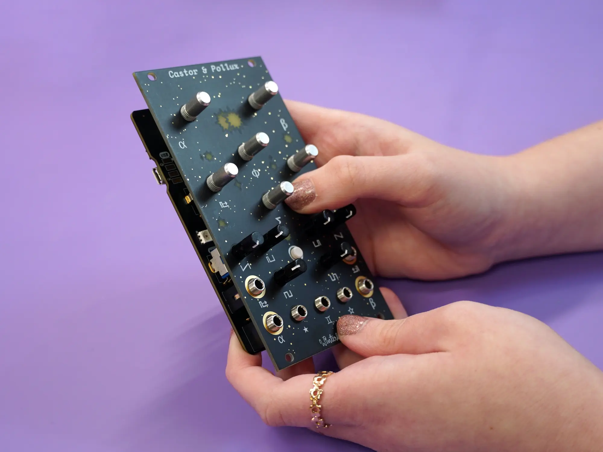
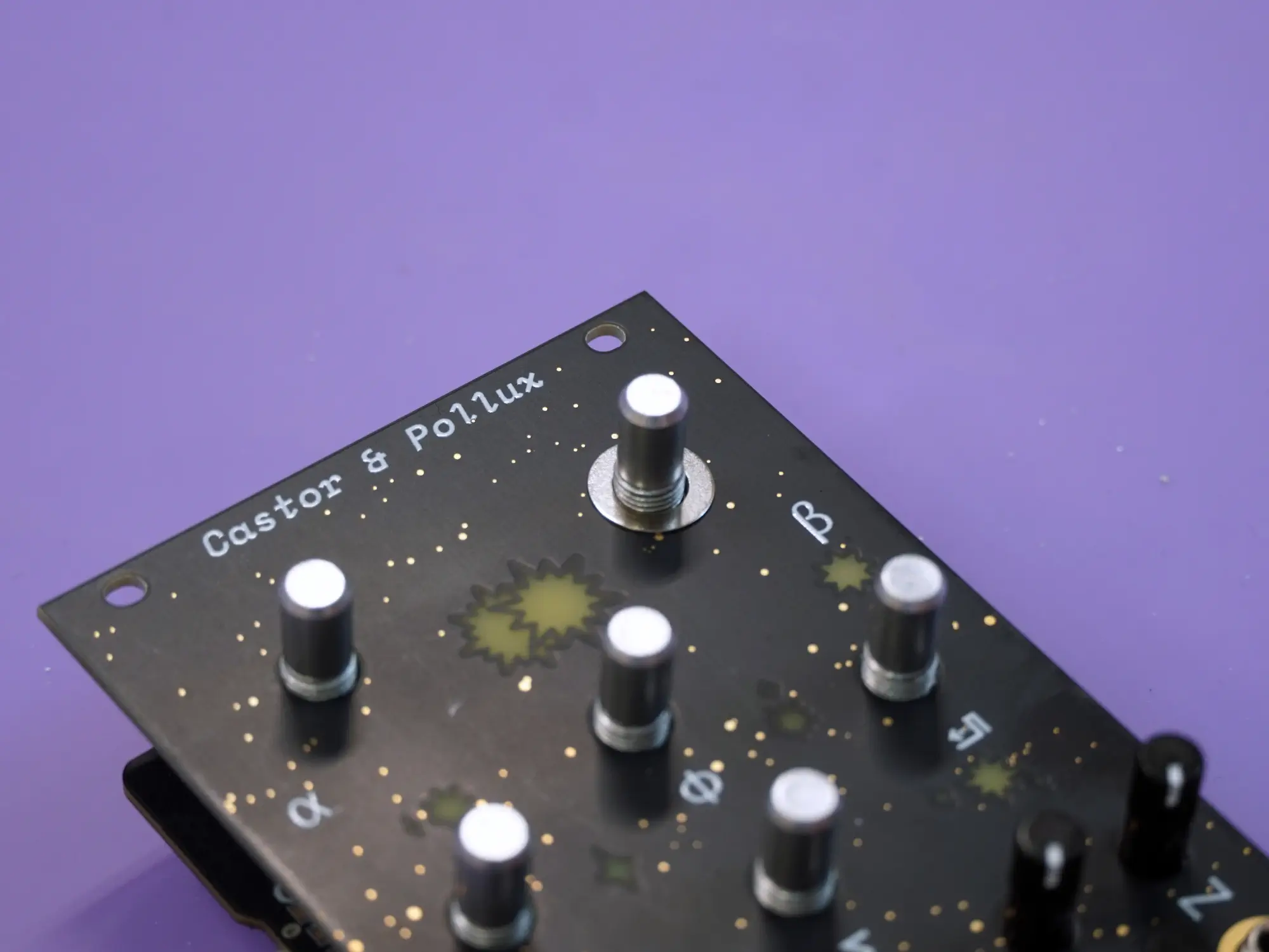
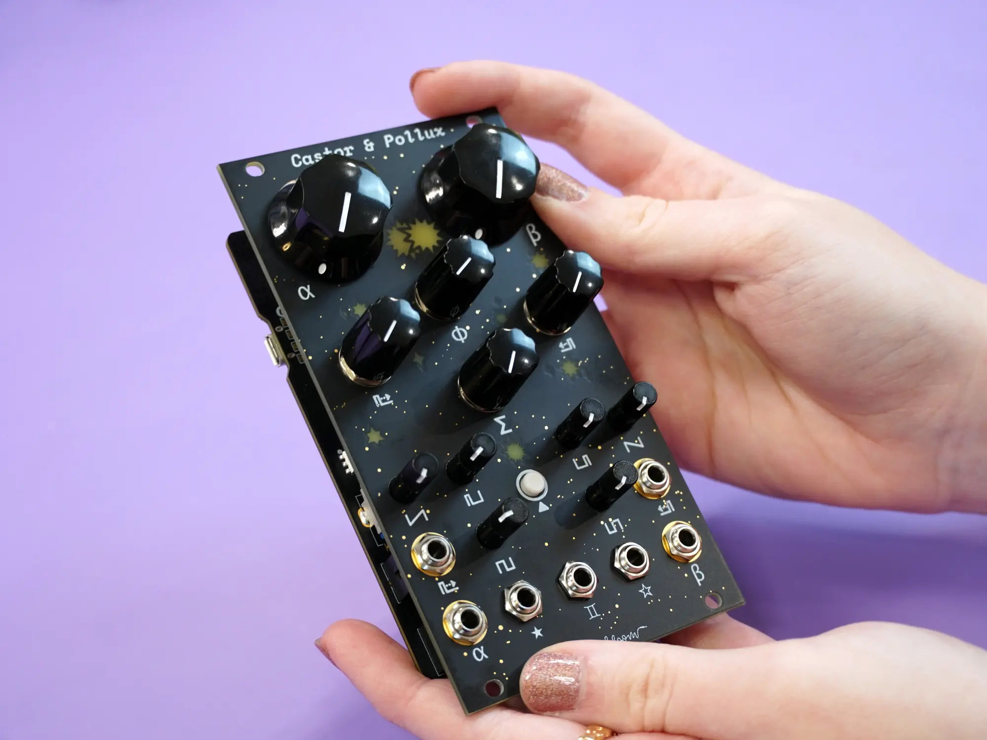
Module completed#
Congrats, you finished building your very own Castor & Pollux!
Continue reading to finish assembling the expander if you'd like. Don't forget to go check out the User's Guide. We'd love to see your work, feel free to tag us on social media - we're @wntrblm on Twitter and Instagram.
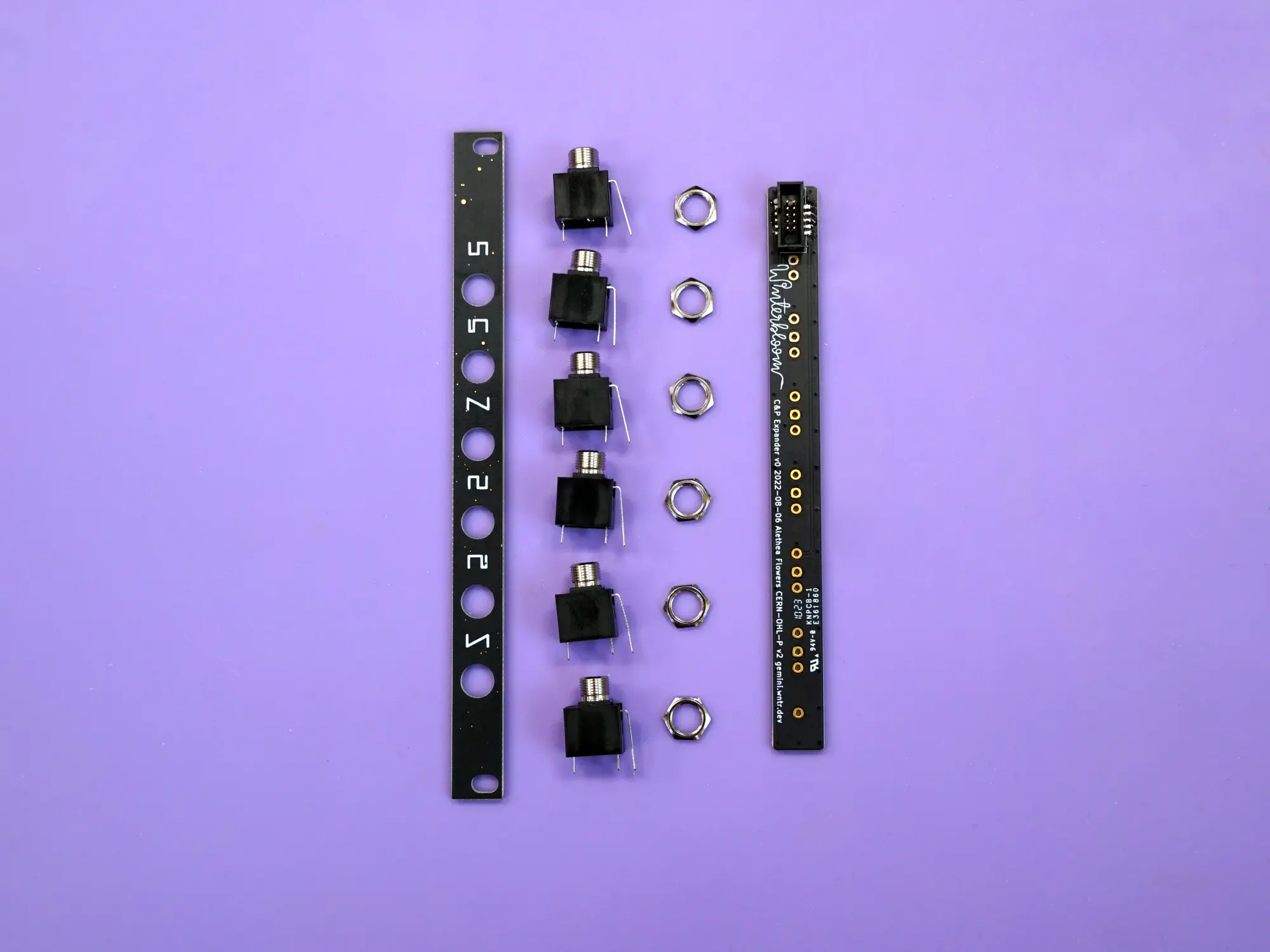
Expander#
To assemble the expander, you'll need the expander faceplate, six 1/8" jacks, six nuts for the jacks, and the expander board.
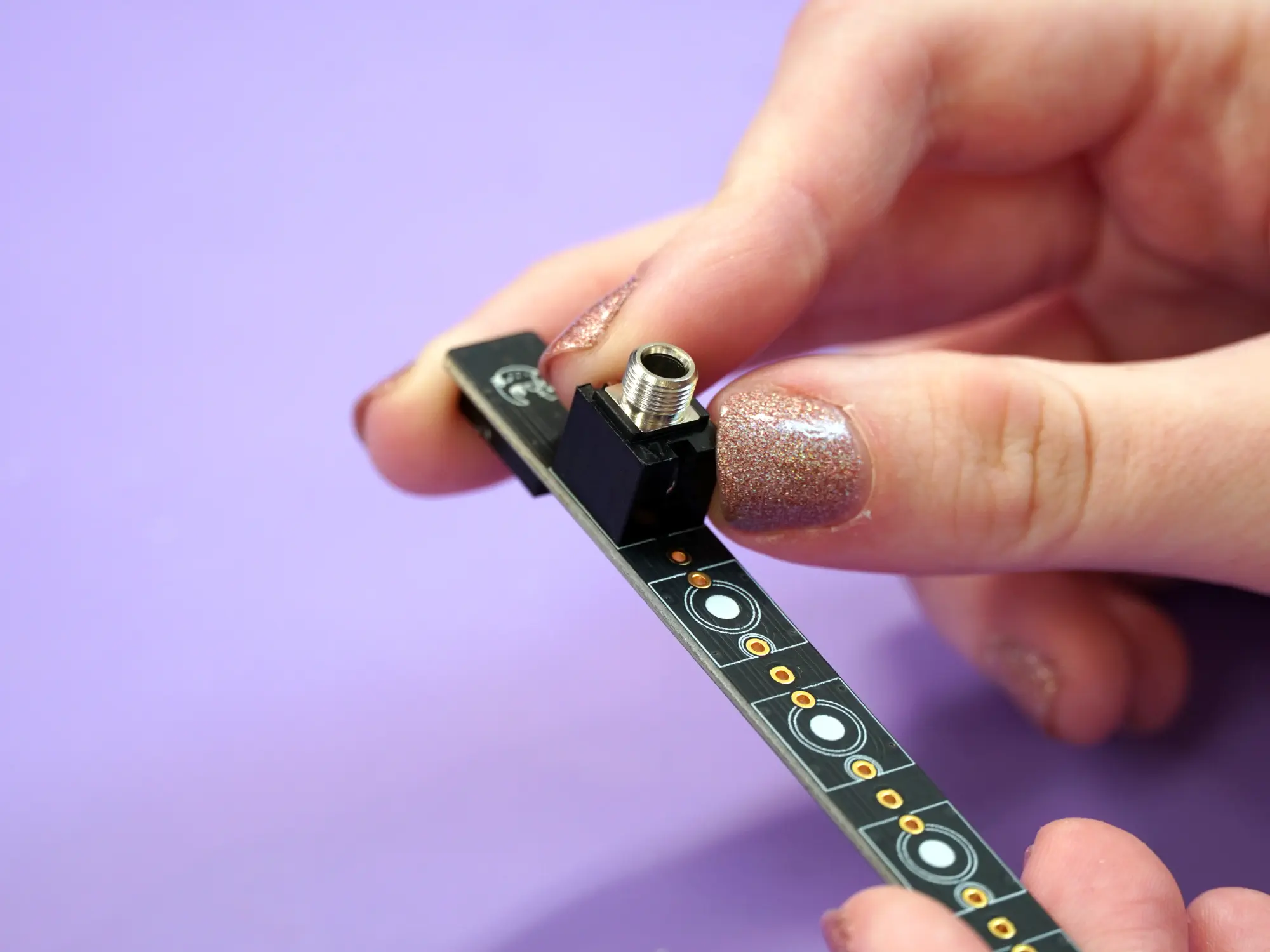
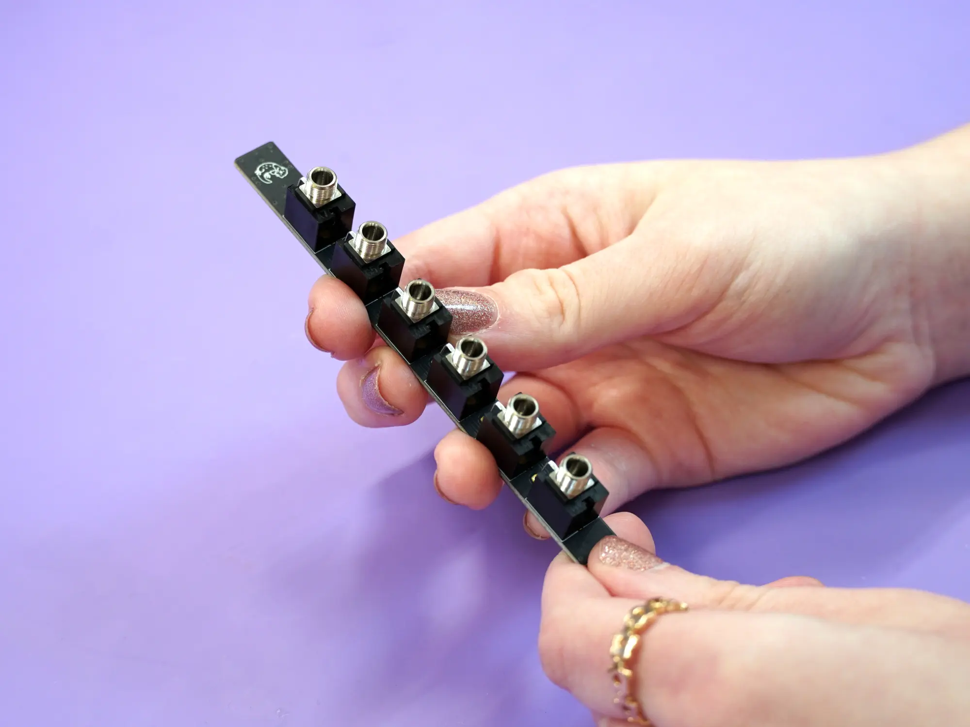
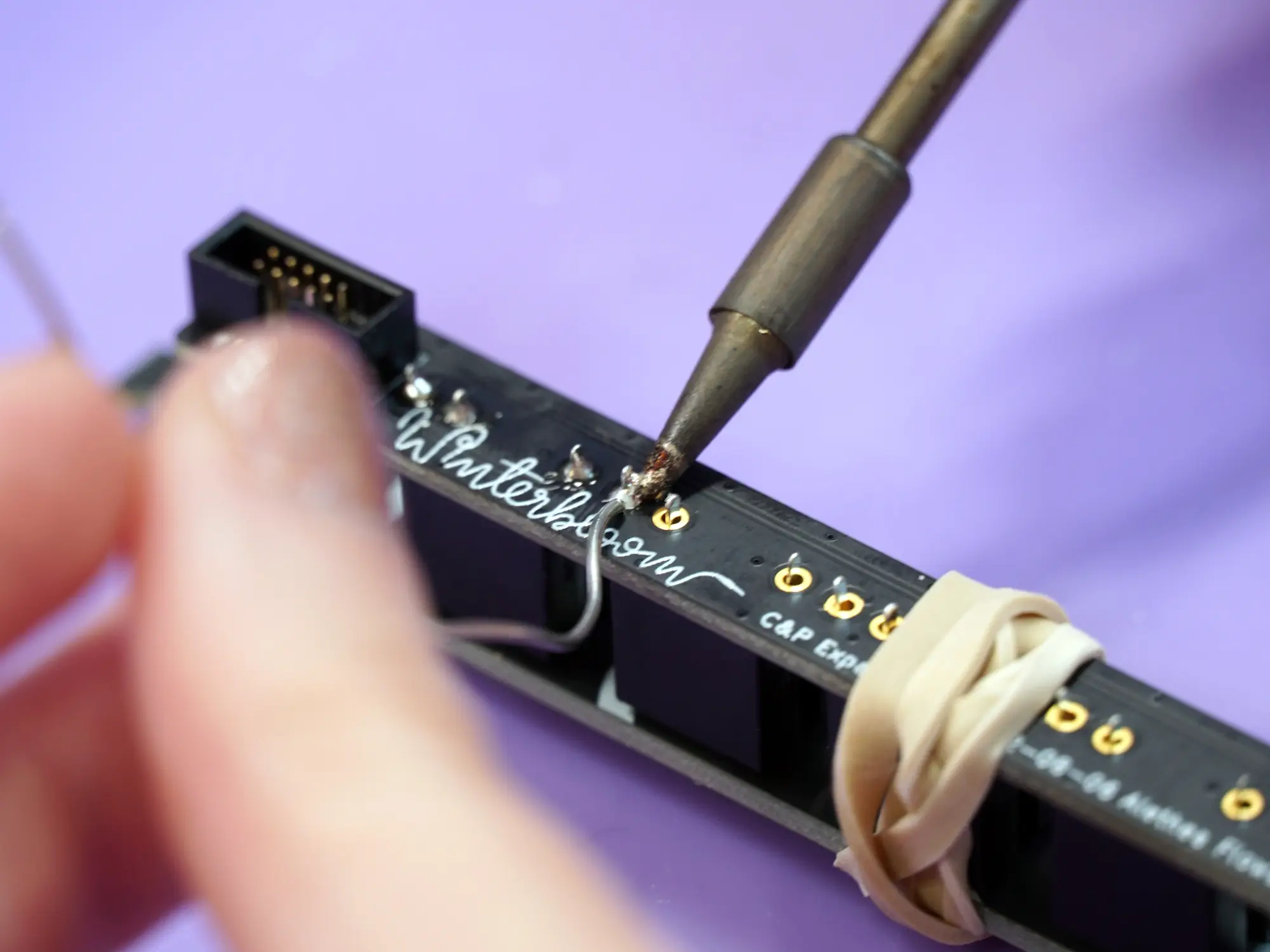
Start by placing all six of the 1/8" jacks onto the front side of the expander board.
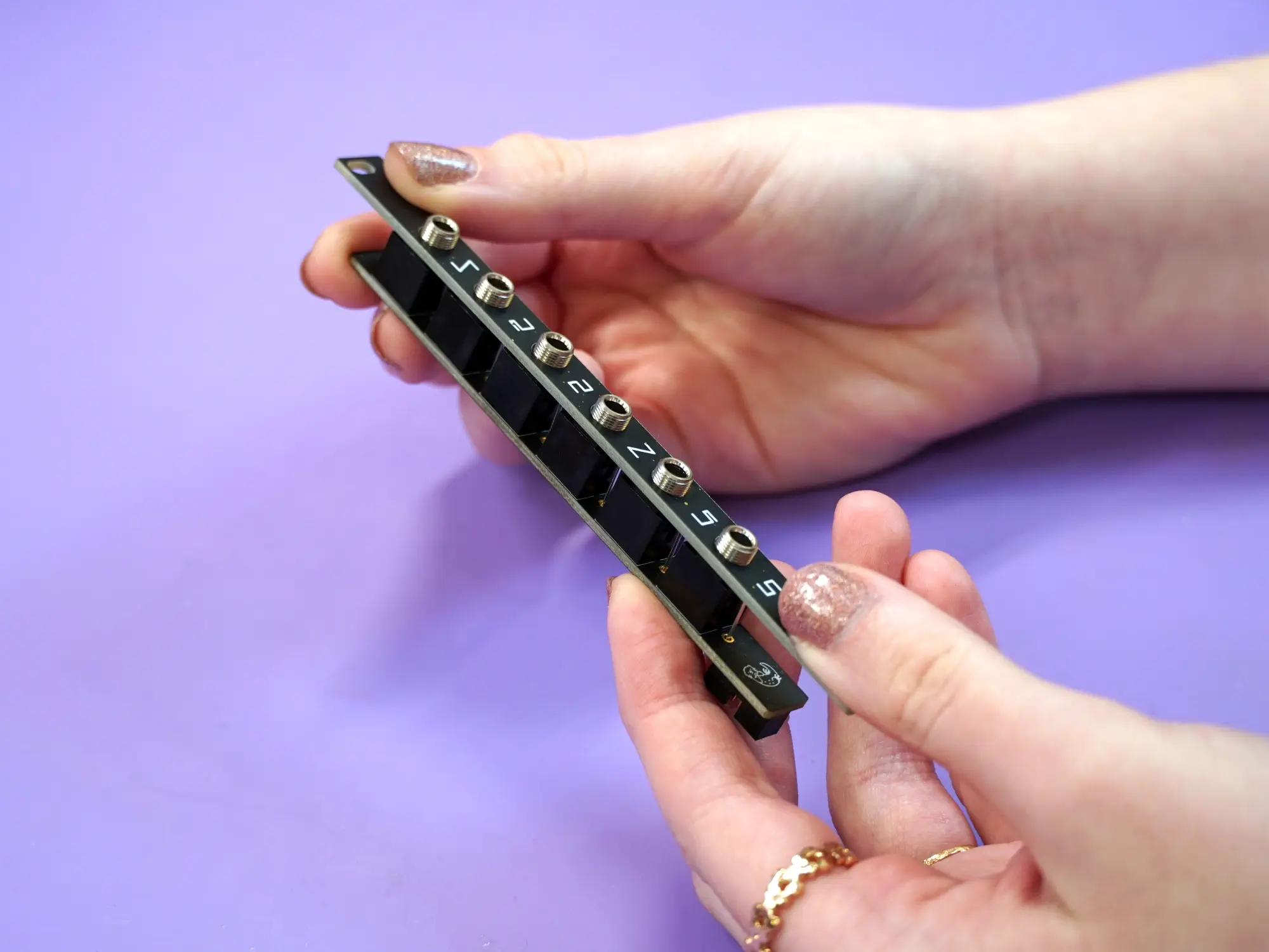
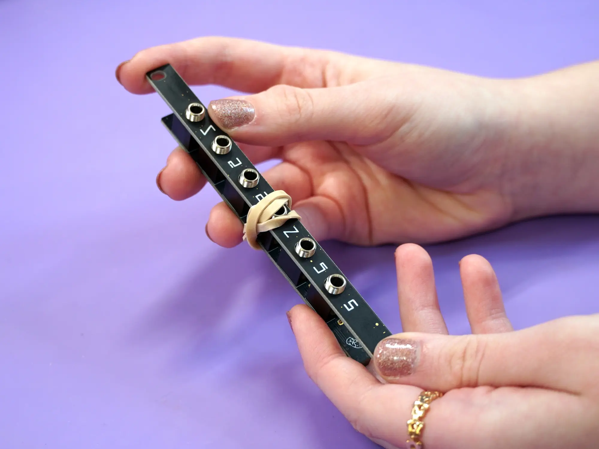
Next, place the faceplate onto the jacks and temporarily hold it in place using a rubber band.
Flip it upside-down and solder all of the jacks into place.
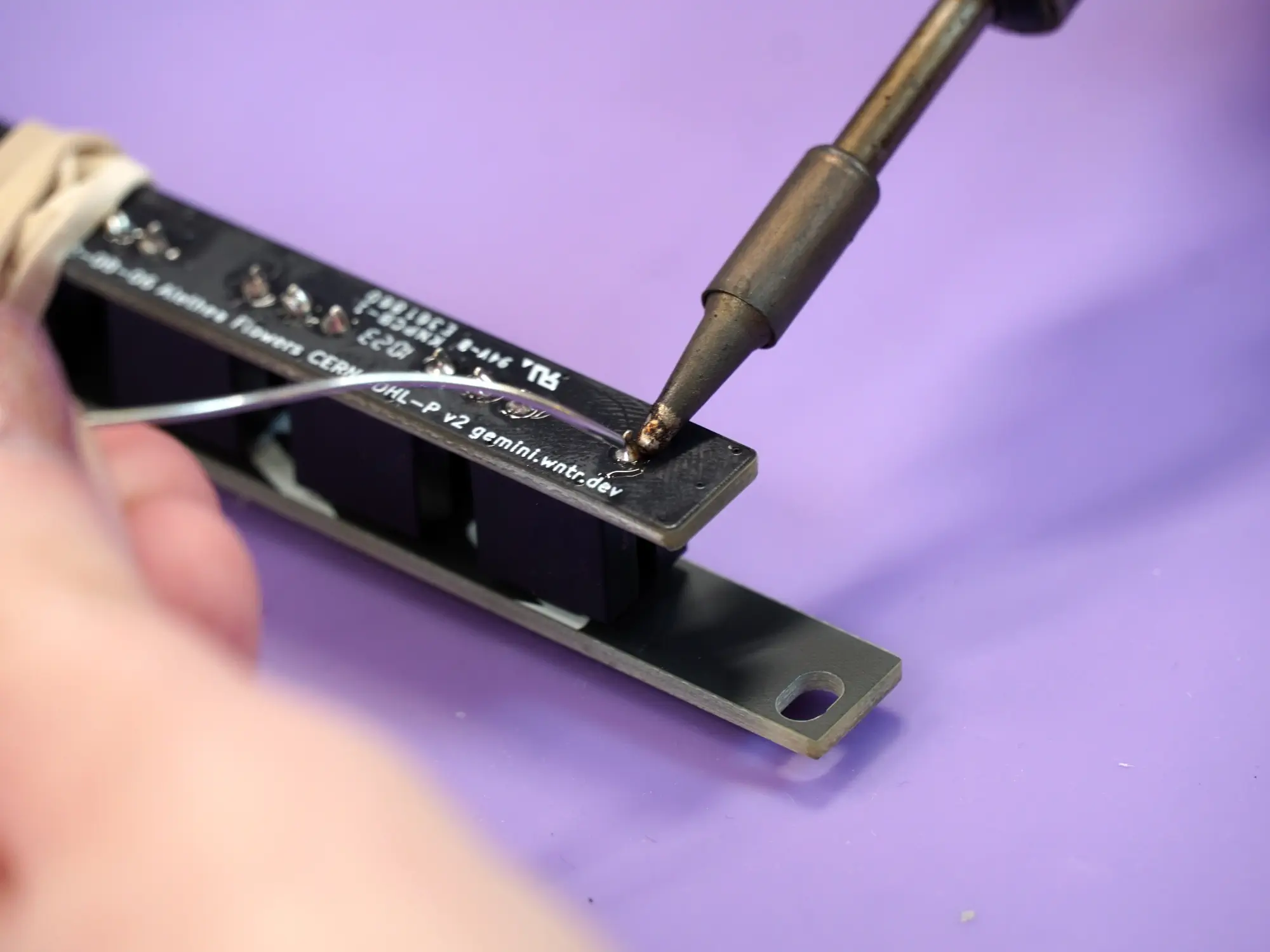
Flip it rightside-up and secure the faceplate using the hex nuts.
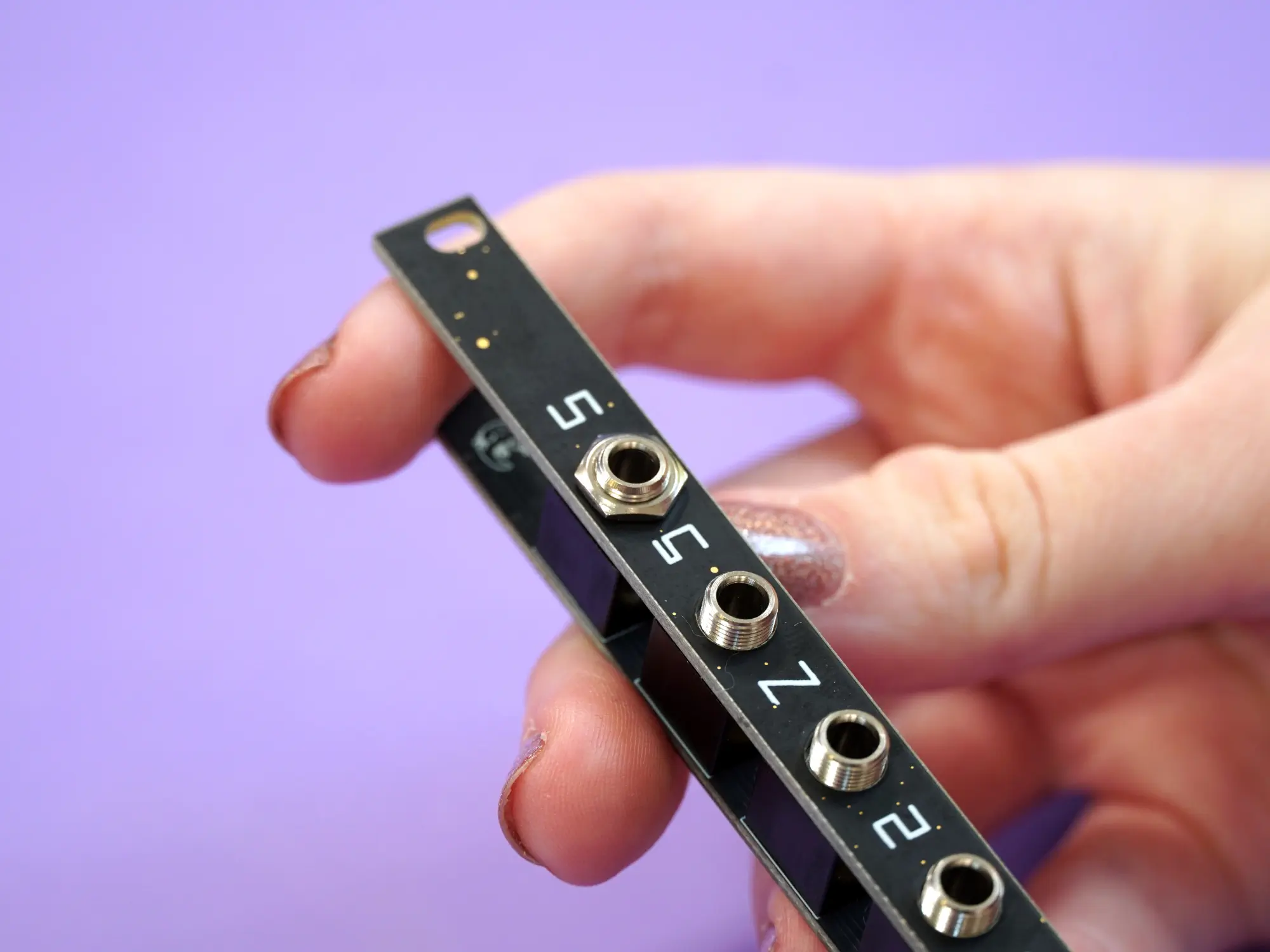
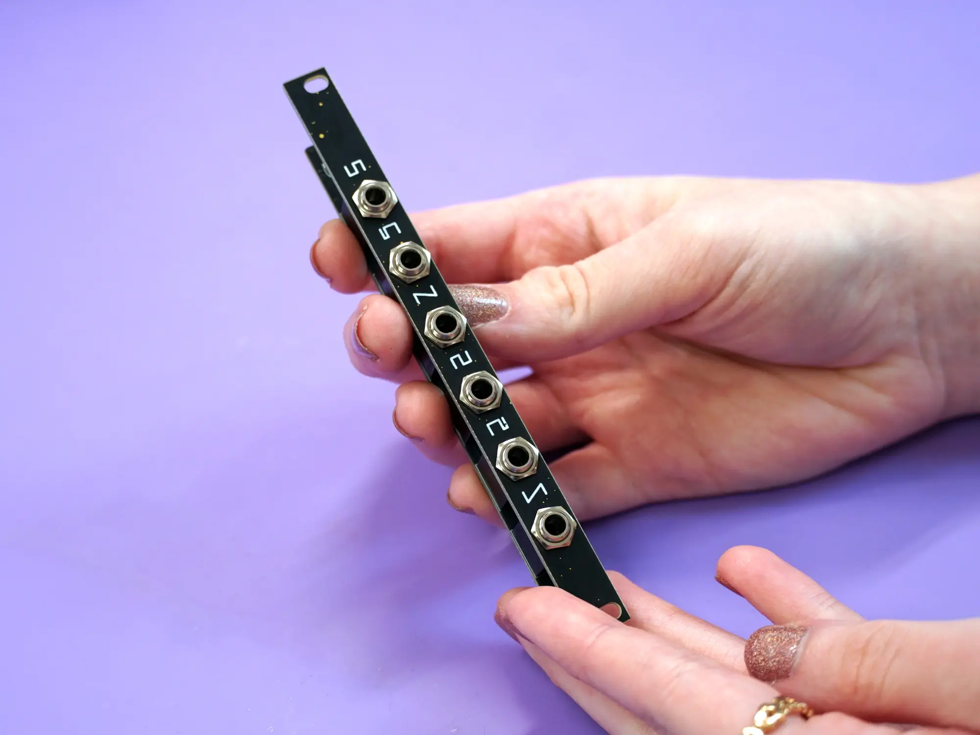
& you're finished!
All done#
Congrats on building your very own Castor & Pollux, we hope you had a lovely time! Don't forget to go check out the User's Guide. We'd love to see your work, feel free to tag us on social media - we're @wntrblm on Twitter and Instagram.
If you have any feedback or ran into any issues, feel free to drop us an email at support@winterbloom.com or file a issue on GitHub.